Augmented reality motorcycle helmet

a technology of display system and motorcycle helmet, which is applied in the field of display system for motorcycle helmets, can solve the problems of reducing the field of view of the rider, limiting the amount of information that can be communicated to the rider, and introducing a beam splitter in the limited space between the rider's face and the helmet windscreen, so as to reduce the noise of wind buffeting of the helmet, reduce the lift, and reduce the inertial resistance. the effect of small resistan

Inactive Publication Date: 2013-11-21
SKULLY
View PDF13 Cites 147 Cited by
  • Summary
  • Abstract
  • Description
  • Claims
  • Application Information

AI Technical Summary

Benefits of technology

[0005]The present invention comprises a helmet having a battery-operated augmented reality display. According to an illustrative embodiment, the helmet comprises a full-face motorcycle helmet with a look-down micro-display that projects a virtual image in-line with the helmet's chin bar (which is space that is already obstructed from the motorcyclist's field of view.) In order to accommodate the power requirements of the micro-display and associated processor, a battery pack consisting of 4 lithium ion batteries each rated at 2200 mAh for a total capacity of 8800 mAh housed within a crescent-shaped housing that is attached to the rear of helmet at the base of the motorcyclist's skull. This unique battery mounting position puts the center of mass of the helmet as close as possible to the base of the neck so that, despite the mass of the batteries, the helmet provides little inertial resistance to quick movements of the head. In the illustrative embodiment, the helmet includes a wind turbine that operates to charge the batteries when the helmet is exposed to a wind blast of greater than approximately 10 mph. Exhaust from the turbine is then deducted through the helmet to cool the battery pack and / or the motorcyclist's head. The turbine is controllable so that at low speeds and high ambient temperatures the turbine operates as a circulating fan to provide ventilation to cool the motorcyclist's head. The helmet further includes a three axis digital gyroscope mounted to the helmet controller board which (1) provides a control input to a controller for operating a steerable headlight of the motorcycle to track the rider's head movements; and (2) in the event of a rapid deceleration possibly indicating an accident, provides acceleration output to an algorithm that will contact emergency responders if the rider is non-responsive. In the illustrative embodiment, the helmet further comprises a 170 degree rear-view camera mounted within an aerodynamic fairing on the back of the helmet. The rear-view camera eliminates blind spots behind the rider's head while the aerodynamic fairing reduces lift and reduces wind buffeting noise of the helmet.

Problems solved by technology

For motorcycles, however, installing a beam splitter in the limited space between the rider's face and the helmet windscreen presents significant design obstacles.
This approach, however, severely limits the amount of information that can be communicated to the motorcycle rider and results in a reduction of the rider's field of view.
Additionally, as the demand for more and more real-time display of information increases, the processor speed and power consumption necessary to accommodate the demands also increases.
This is not an ideal implementation for a motorcycle helmet since a cable connected between the motorcyclist's helmet and a belt-mounted battery would be cumbersome especially with the exposed cable subjected to windblast at high speeds.

Method used


Image

  • Augmented reality motorcycle helmet
  • Augmented reality motorcycle helmet
  • Augmented reality motorcycle helmet

Examples


Embodiment Construction

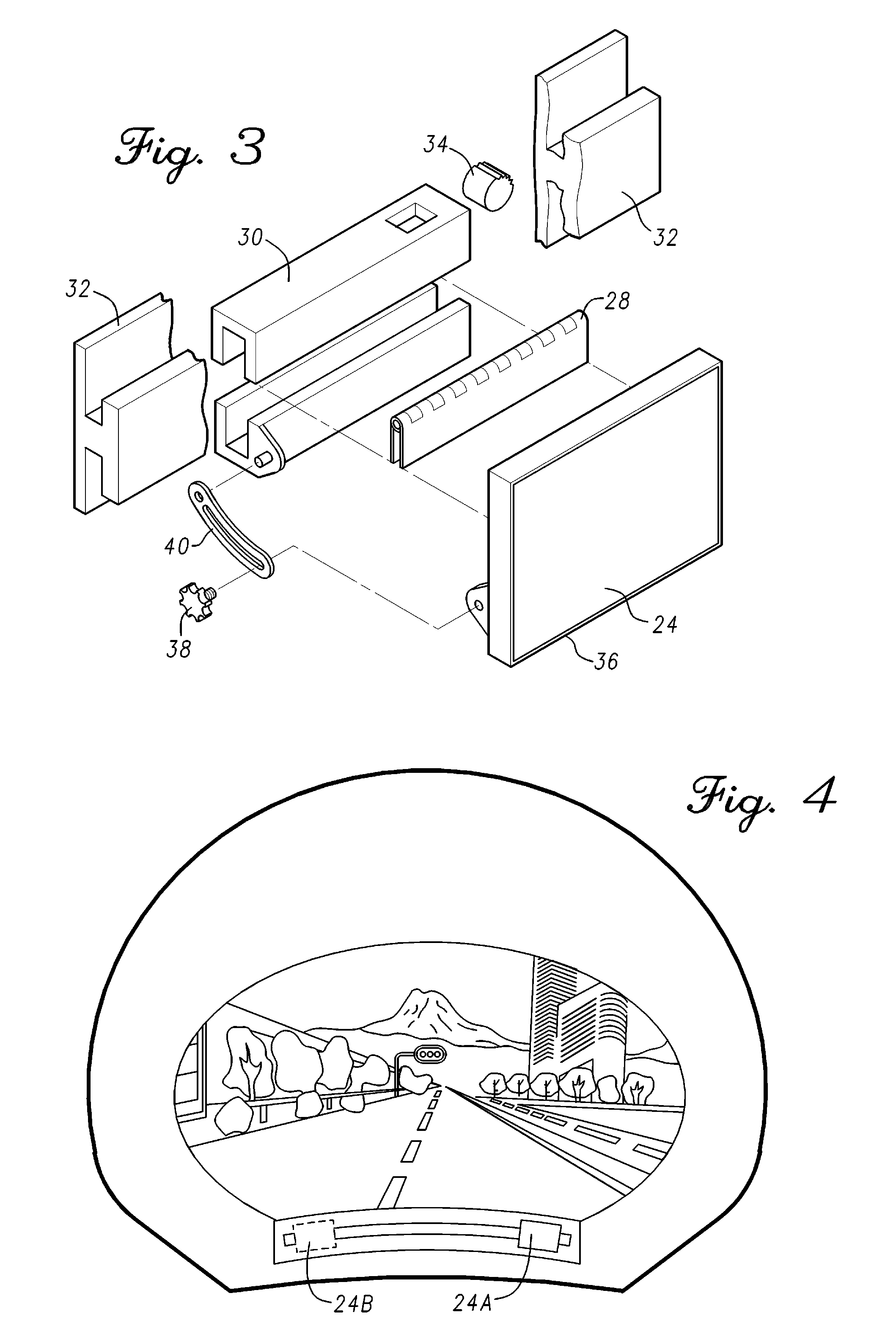
[0017]The drawing figures are intended to illustrate the general manner of construction and are not necessarily to scale. In the detailed description and in the drawing figures, specific illustrative examples are shown and herein described in detail. It should be understood, however, that the drawing figures and detailed description are not intended to limit the invention to the particular form disclosed, but are merely illustrative and intended to teach one of ordinary skill how to make and / or use the invention claimed herein and for setting forth the best mode for carrying out the invention.

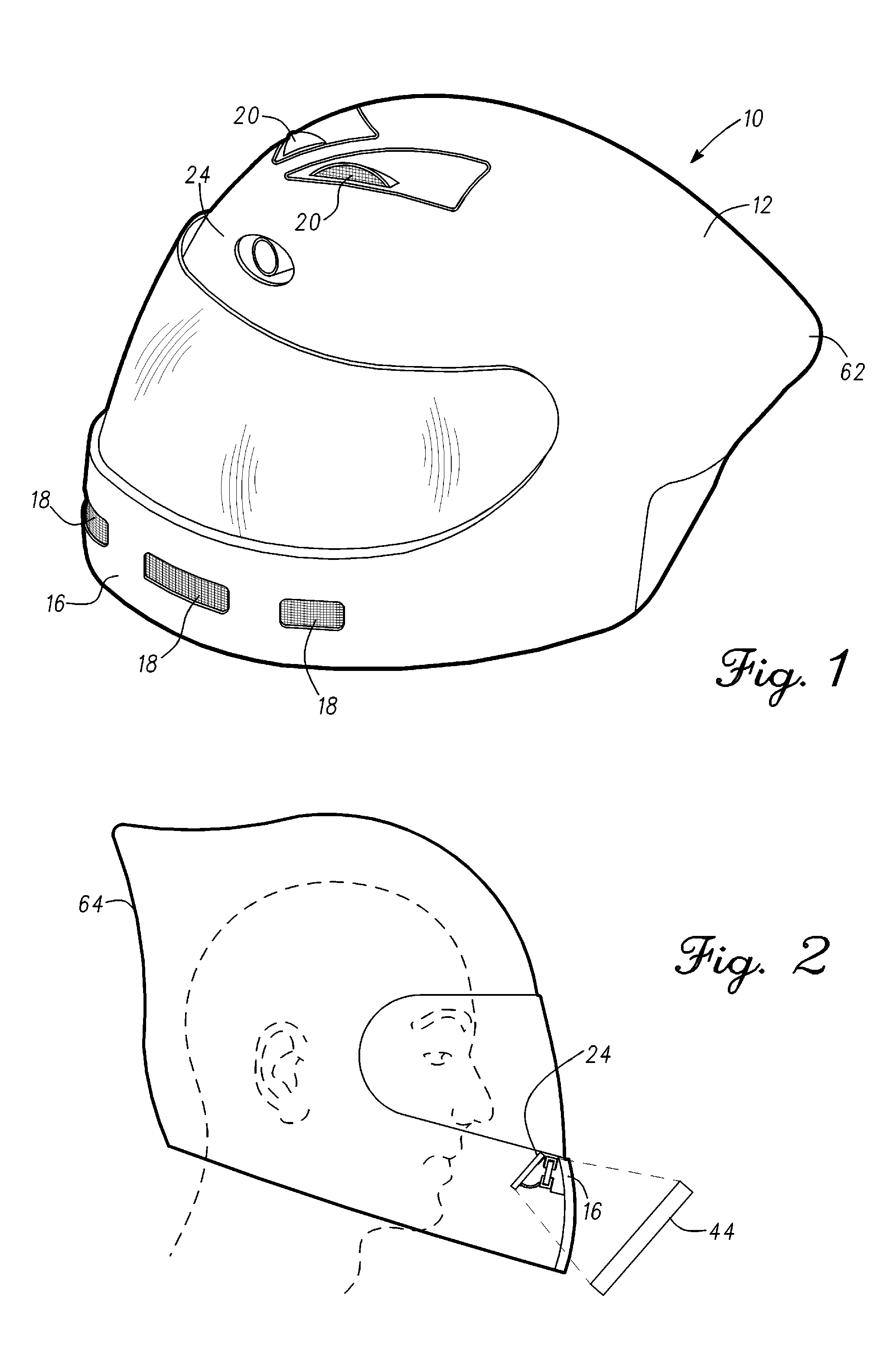
[0018]With reference to the drawing figures and in particular FIG. 1 there is shown a helmet 10 incorporating features of the present invention. Although helmet 10 is depicted as a motorcycle helmet, a helmet incorporating features of the present invention may be implemented as a bicycle helmet, industrial safety helmet, military or other helmet without departing from the scope of the invention...


PUM


Abstract

An augmented-reality helmet comprises a full-face motorcycle helmet with a look-down micro-display that projects a virtual image in-line with the helmet's chin bar. In order to accommodate the power requirements, the helmet includes a battery pack mounted at the base of the motorcyclist's skull. A wind turbine charges the batteries. Exhaust from the turbine is then deducted through the helmet to cool the battery pack and/or the motorcyclist's head. The turbine is controllable so that it can operate as a circulating fan to provide ventilation. A digital gyroscope provides a control input to a controller for operating a steerable headlight of the motorcycle to track the rider's head movements; and provides acceleration output to an algorithm that will contact emergency responders if the rider is non-responsive after a collision. A 170 degree rear-view camera is mounted within an aerodynamic fairing on the back of the helmet.

Description

BACKGROUND OF THE INVENTION[0001]This invention relates generally to display systems for helmets and in particular for display systems for motorcycle helmets.[0002]Heads-up displays have been suggested for implementation in a multitude of transportation applications including automobiles, aircraft and motorcycles. Heads-up displays typically comprise an image projector, an optical collimator; and a beam splitter (combiner). The beam splitter is typically an angled flat piece of transparent or partially reflective material located directly in front of the viewer. The beam splitter reflects the image from the image projector in such a way that the user is able to see the field of view and the projected image at the same time. The optical collimator focuses the image from the image projector into parallel rays of light so that the user sees a virtual image that appears to be at an infinite distance.[0003]The necessity of having a beam splitter as part of a heads-up display causes littl...

Claims


Application Information

Patent Timeline
Patent Type & Authority Applications(United States)
IPC IPC(8): A42B3/04
CPCA42B3/0406A42B3/0426A42B3/0493A42B3/286A42B3/30G02B2027/0138G02B27/0176A42B3/042G06V20/58A42B3/0446A42B3/046A42B3/221A42B3/28G02B27/0172G02B27/0179G02B2027/0159G02B2027/0183G06T19/006
Inventor WELLER, MARCUS D.SHREEVE, BRIAN ROBERTROBERTS, MICHAEL JAMES
Owner SKULLY
Why Eureka
Try Eureka