A kind of composite material brake drum and preparation method thereof

A composite material, brake drum technology, applied in the direction of brake type, brake components, metal material coating process, etc. The problem is that the heat dissipation performance of the type brake is poor, and the effect of high rigidity, excellent thermal fatigue performance and reduced inertial resistance is achieved.

Active Publication Date: 2021-02-02
天宜上佳(天津)新材料有限公司
View PDF9 Cites 0 Cited by
  • Summary
  • Abstract
  • Description
  • Claims
  • Application Information

AI Technical Summary

Problems solved by technology

[0004] Compared with disc brakes, drum brakes have poor braking efficiency and heat dissipation
The braking force stability of drum brakes is poor, and the braking force varies greatly on different road surfaces, which is not easy to control
The heat dissipation performance of the drum brake is poor, and a large amount of heat will be accumulated during the braking process. Decreased dynamic efficiency
At present, the commonly used brake drum is made of gray cast iron (HT250), which has poor high temperature fatigue performance and is prone to cracking and explosion when it is repeatedly heated and watered, endangering the safety of personnel and vehicles.

Method used


Image

  • A kind of composite material brake drum and preparation method thereof
  • A kind of composite material brake drum and preparation method thereof
  • A kind of composite material brake drum and preparation method thereof

Examples


Embodiment 1

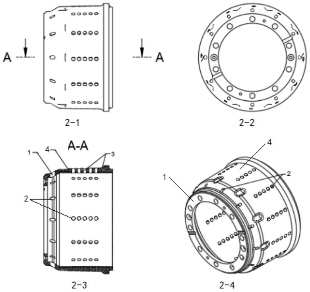
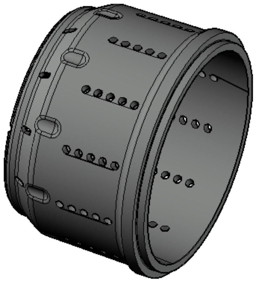
[0051] The composite material brake drum provided in this embodiment is as figure 2 and 3 As shown, the brake drum body includes a friction body 4 and a base 1. On the friction body 4, 12 groups of chip removal holes 2 are evenly distributed side by side. The number of each group of chip removal holes 2 is 6, and each group of chip removal holes 2 They are all parallel to the central axis of the composite material brake drum, and the wall thickness of the friction body is 16mm.

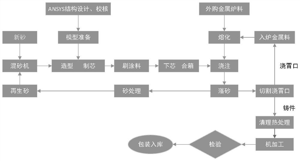
[0052] The production process of composite material brake drum is as follows: figure 1 shown.

[0053] Using ANSYS structure optimization and strength check, the core box and cavity model are designed.

[0054] Select the braking molding equipment to make the pouring cavity, and use the core shooter to make the sand core.

[0055] ZG35CrMoV alloy steel (strength ≥ 800MPa) is used as the base material of the brake drum.

[0056] The alloy steel is smelted in advance by using appropriate melting equ...

Embodiment 2

[0064] The production technological process of present embodiment composite material brake drum is as follows figure 1 shown.

[0065] Using ANSYS structure optimization and strength check, the core box and cavity model are designed.

[0066] Select the braking molding equipment to make the pouring cavity, and use the core shooter to make the sand core.

[0067] ZG35CrMoV alloy steel (strength ≥ 800MPa) is used as the base material of the brake drum.

[0068] The alloy steel is smelted in advance by using appropriate melting equipment, and the obtained alloy steel solution is used for standby.

[0069] Select a suitable carburizing agent for use, graphite powder 40wt%, ferrosilicon powder 18wt%, binder 2wt%, suspension stabilizer 4.5wt%, auxiliary agent 0.5wt% and ethanol 35wt%.

[0070] The above-mentioned carburizing agent is coated on the surface of the sand core (the surface of the sand core is in contact with the inner surface of the brake drum).

[0071] Using the gr...

Embodiment 3

[0076] The production technological process of present embodiment composite material brake drum is as follows figure 1 shown.

[0077] Using ANSYS structure optimization and strength check, the core box and cavity model are designed.

[0078] Select the braking molding equipment to make the pouring cavity, and use the core shooter to make the sand core (the surface of the sand core is in contact with the inner surface of the brake drum).

[0079] ZG35CrMoV alloy steel (strength ≥ 800MPa) is used as the base material of the brake drum.

[0080] The alloy steel is smelted in advance by using appropriate melting equipment, and the obtained alloy steel solution is used for standby.

[0081] Select a suitable carburizing agent for future use, graphite powder 45wt%, ferrosilicon powder 20wt%, binder 4wt%, suspension stabilizer 2wt%, auxiliary agent 0.5wt% and ethanol 28.5wt%.

[0082] The above-mentioned carburizing agent is coated on the surface of the sand core (the surface of ...


PUM

PropertyMeasurementUnit
particle size (mesh)aaaaaaaaaa
thicknessaaaaaaaaaa

Abstract

The invention discloses a composite material brake drum and a preparation method thereof in the technical field of vehicle brake drums. The brake drum made of composite material includes a brake drum body, which is integrally cast from low-alloy cast steel, and a composite layer is provided on the inner surface of the brake drum body, and the composite layer includes, C 3.3 ‑3.6%; Si 2.2‑2.7%; Mn 0.4‑0.7%; S≤0.015%; P≤0.020%; Cr 0.6‑1.1%; Mo 0.12‑0.25%. The composite material brake drum of the present invention uses low-alloy steel as the matrix material, has high tensile strength and impact toughness, is not easy to crack during use, and has high safety performance; the material of the composite layer on the inner surface of the dynamic drum is close to that of gray cast iron, so that The composite brake drum has self-lubricating effect and good wear resistance; at the same time, due to the alloy composition in the low-alloy steel on the inner surface of the brake drum, the wear of the brake drum is only half of that of gray cast iron under the same braking force, and the service life of the brake drum is longer. Long; gray cast iron is replaced by composite materials, the performance of the brake drum is better, the structure is lighter, and the product quality is stable.

Description

technical field [0001] The invention relates to the technical field of vehicle brake drums, in particular to a composite material brake drum and a preparation method thereof. Background technique [0002] Drum brakes, also called block brakes, are a commonly used brake product that can slow down, stop or keep moving parts at a stop, and play a role in protecting driving safety. The drum brake uses the brake transmission mechanism to make the brake shoe press the brake friction plate against the inner side of the brake drum, thereby generating braking force, decelerating the wheel or stopping the wheel within the shortest distance according to the need, so as to ensure driving safety and ensure The car is reliably parked and cannot slide automatically. [0003] The mainstream of drum brakes is the internal tension type, and its brake block (brake shoe) is located on the inner side of the brake wheel. When braking, the brake block opens outwards and rubs against the inner sid...

Claims


Application Information

Patent Timeline
Patent Type & Authority Patents(China)
IPC IPC(8): F16D65/10F16D65/827C22C37/06C22C37/10C22C38/02C22C38/04C22C38/22C23C8/64B22C3/00B22D23/04
CPCB22C3/00B22D23/04C22C37/06C22C37/10C22C38/02C22C38/04C22C38/22C23C8/64F16D65/0031F16D65/10F16D65/827F16D2200/0021F16D2250/0007
Inventor 吴佩芳释加才让崔新亮王灿张芳杰郑仕琦
Owner 天宜上佳(天津)新材料有限公司
Why Eureka
Try Eureka