Sealing member
- Summary
- Abstract
- Description
- Claims
- Application Information
AI Technical Summary
Benefits of technology
Problems solved by technology
Method used
Image
Examples
first embodiment
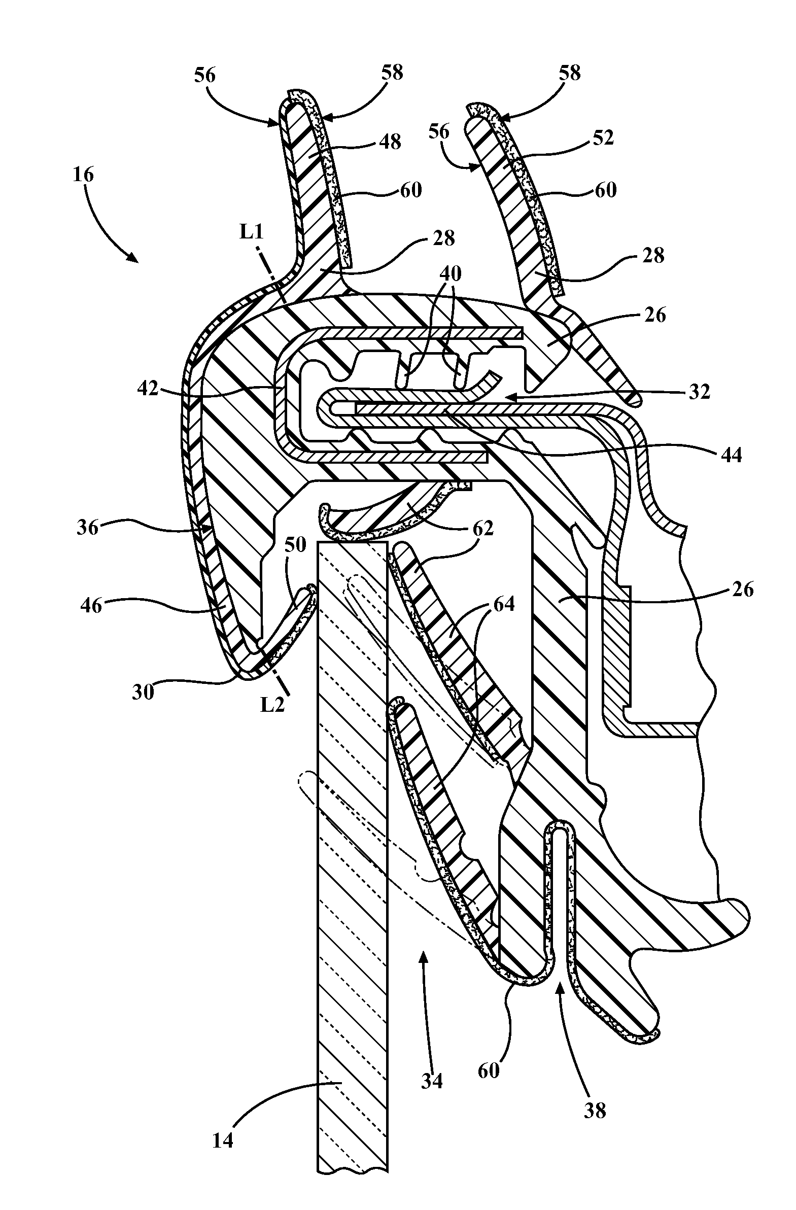
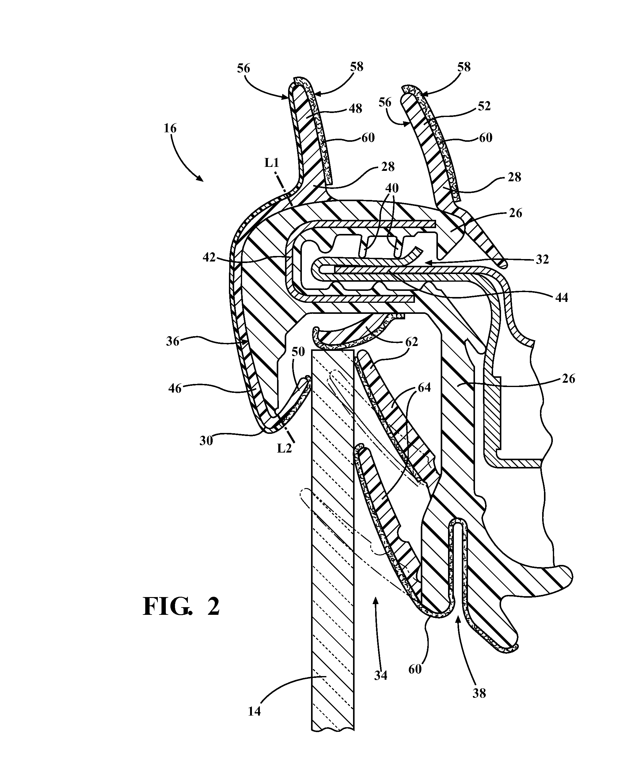
[0020]Referring to FIG. 2, a cross-sectional view of the sealing member 16 of the window seal assembly 10 is shown. The sealing member 16 includes a first co-extrusion layer 26 formed from a first elastomeric composition, a second co-extrusion layer 28 formed from a second elastomeric composition, and a third co-extrusion layer 30 formed from the TPV composition.
[0021]The first co-extrusion layer 26 defines a mounting channel 32, a window channel 34, and a front face 36 spaced from the mounting channel 32 and the window channel 34. In a typical embodiment, the front face 36 is substantially parallel to window channel 34 and extends from a first reference line L1 to second reference line L2. The window channel 34 is adjacent to the mounting channel 32. Further, the first co-extrusion layer 26 defines a bottom channel 38 adjacent and substantially parallel to the window channel 34.
[0022]The mounting channel 32 contains a plurality of gripping fins 40 for holding and securing the seali...
second embodiment
[0038]Referring to FIG. 3, a cross-sectional view of the sealing member 16 of the window seal assembly 10 is shown. The sealing member 16 of this embodiment also includes the first co-extrusion layer 26 formed from the first elastomeric composition, the second co-extrusion layer 28 formed from the second elastomeric composition, and the third co-extrusion layer 30 formed from the TPV composition. The third co-extrusion layer has a face portion disposed on said front face of said first co-extrusion layer (extending from L1 to L2) for covering segments of first co-extrusion layer that are visible from an exterior of the vehicle. In this embodiment, the first sealing lip 48 is formed from the TPV composition, i.e., the third co-extrusion layer 30 and disposed on the first co-extrusion layer 26 abutting the face portion and extending away from the first co-extrusion layer 26 towards a distal end.
[0039]In contrast to the first embodiment, in this second embodiment the placement of the th...
third embodiment
[0043]In this embodiment, the trim member 66 which has a front face 74, a main body 76, and a first and a second stem 78, 80, received within the channels 68, 70 of the sealing member 16. More specifically, the first and second stem 78, 80 are received within the channels 68, 70 to secure the trim member 66 to the sealing member 16. FIG. 4A is a cross-sectional view of the sealing member 16 with the trim member 66 shown spaced from the sealing member 16 whereas FIG. 4B is a cross-sectional view of the sealing member 16 of FIG. 4A showing the trim member 66 coupled to the sealing member 16.
[0044]A method of forming the sealing member 16 of the subject invention is also disclosed. The method includes the steps of co-extruding the first elastomeric composition to form the first co-extrusion layer 26, co-extruding the second elastomeric composition to form the second co-extrusion layer 28, and co-extruding the TPV composition to form the third co-extrusion layer 30.
[0045]In one embodime...
PUM
| Property | Measurement | Unit |
|---|---|---|
| Percent by mass | aaaaa | aaaaa |
| Percent by mass | aaaaa | aaaaa |
| Thickness | aaaaa | aaaaa |
Abstract
Description
Claims
Application Information
 - R&D
- Intellectual Property
- Life Sciences
- Materials
- Tech Scout
- Unparalleled Data Quality
- Higher Quality Content
- 60% Fewer Hallucinations
Browse by: Latest US Patents, China's latest patents, Technical Efficacy Thesaurus, Application Domain, Technology Topic, Popular Technical Reports.
© 2025 PatSnap. All rights reserved.Legal|Privacy policy|Modern Slavery Act Transparency Statement|Sitemap|About US| Contact US: help@patsnap.com


