Web member cutting apparatus for cutting web member that has a plurality of fibers including tows and web member cutting method

Active Publication Date: 2013-11-21
UNI CHARM CORP
View PDF60 Cites 8 Cited by
  • Summary
  • Abstract
  • Description
  • Claims
  • Application Information

AI Technical Summary

Benefits of technology

The invention provides a cutting apparatus and a cutting method for cutting a continuous web member with a plurality of fibers into regular intervals. The apparatus and method can suppress the compression-bonding and welding of tows at a target cut position while maintaining high bulkiness of the cut sheet-like product and suppressing wear of the cutting edge.

Problems solved by technology

This may cause a trouble that the cut edges is bound to each other in loops, which results in deterioration of the performance of the brush section (dust trapping performance during cleaning).
Furthermore, if the cut edges are bound to each other in loops, bulkiness of the cleaning web member decreases, which also lowers the performance of the brush section.
Furthermore, due to contact of the cutter blade with the receiver blade during cutting, the cutting edge of the cutter blade is likely to be worn, which shortens the life of the cutter blade.

Method used


Image

  • Web member cutting apparatus for cutting web member that has a plurality of fibers including tows and web member cutting method
  • Web member cutting apparatus for cutting web member that has a plurality of fibers including tows and web member cutting method
  • Web member cutting apparatus for cutting web member that has a plurality of fibers including tows and web member cutting method

Examples


first embodiment

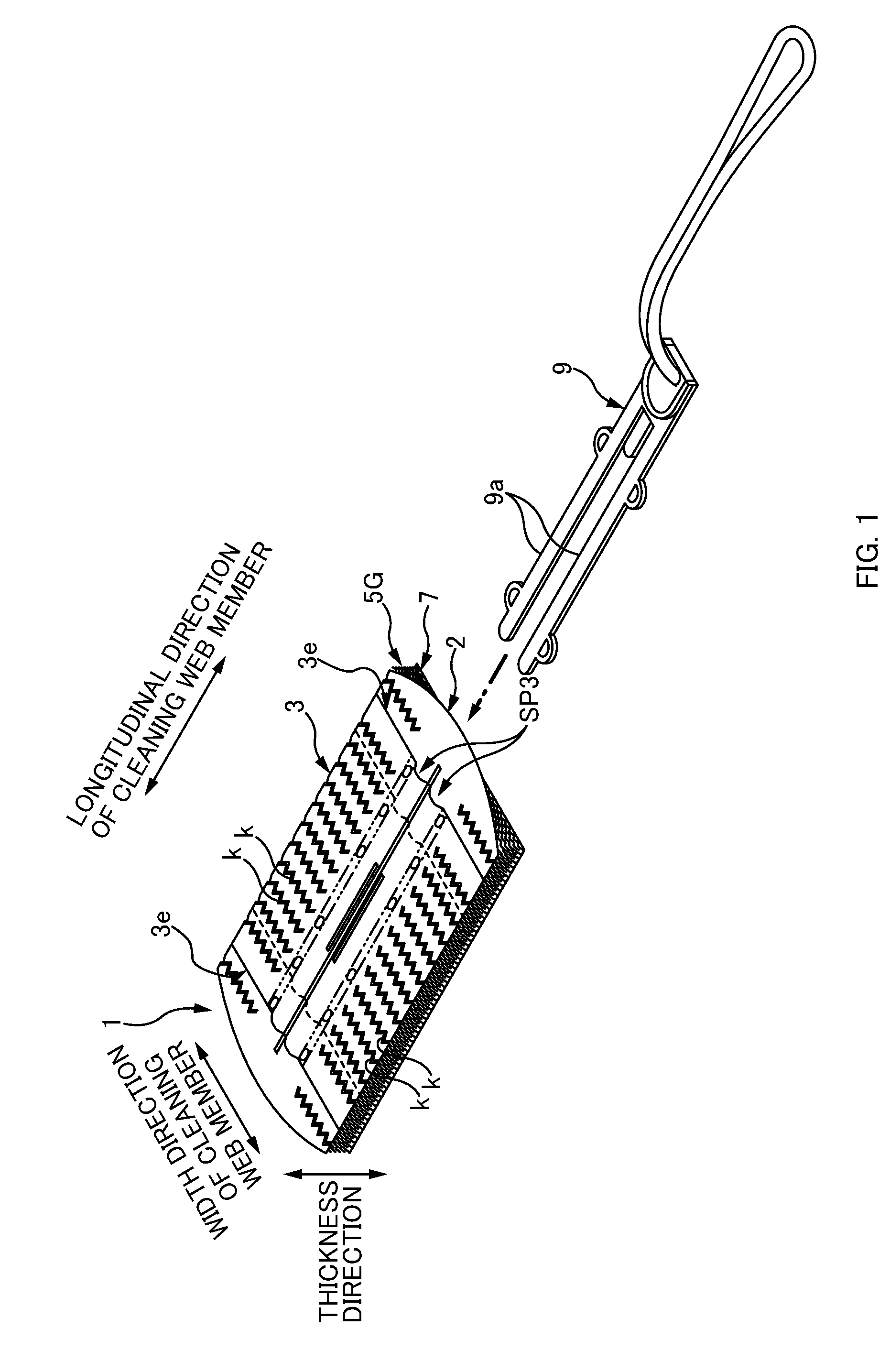
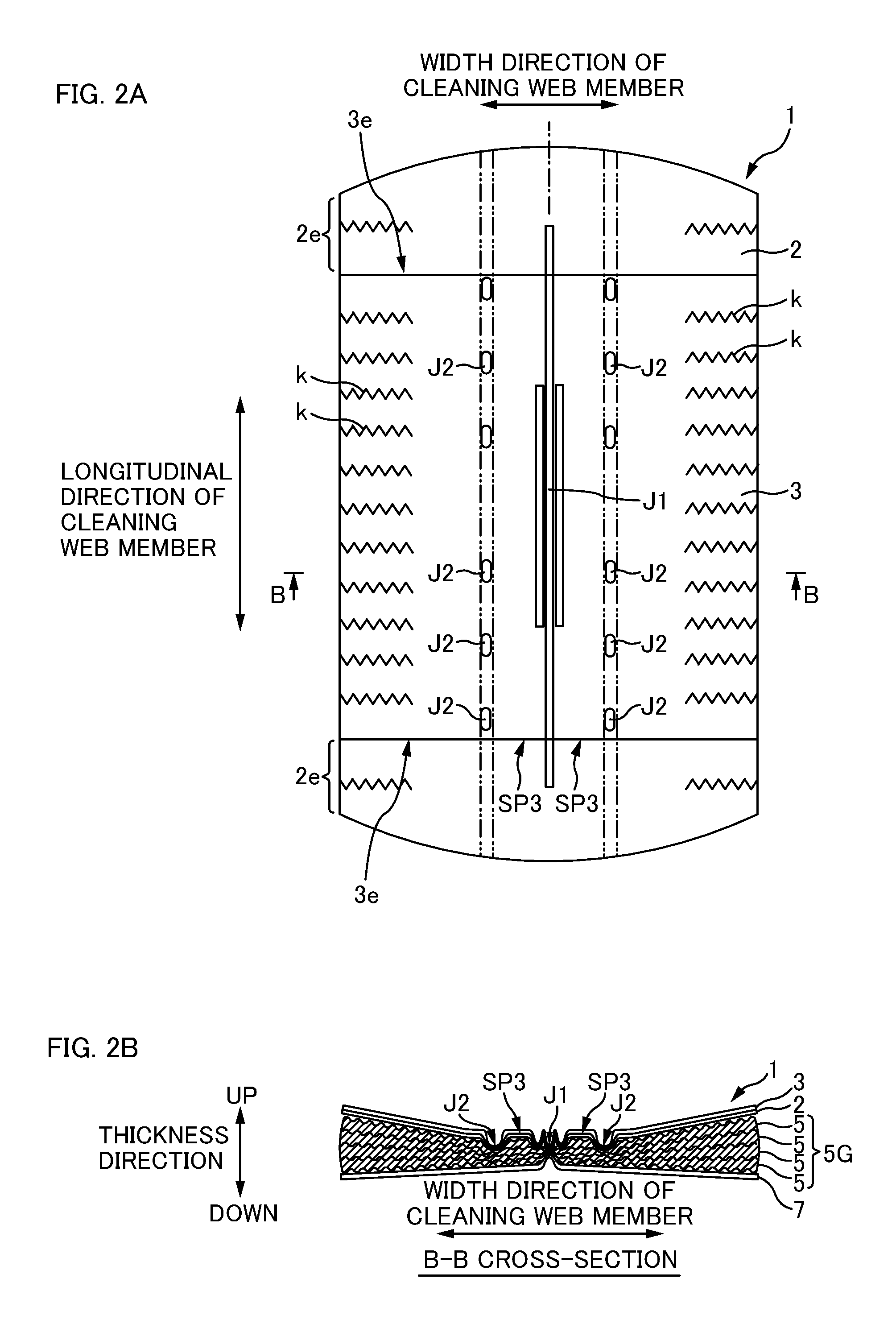
[0105]FIG. 1 is a perspective view of a cleaning web member 1 formed by cutting using a cutting apparatus 10 of the first embodiment. FIG. 2A is a plan view thereof, and FIG. 2B is a cross-sectional view taken along line B-B in FIG. 2A.

[0106]As shown in FIGS. 1 and 2A, the cleaning web member 1 (corresponding to a cut sheet-like product) is substantially in the shape of a rectangle having a longitudinal direction and a width direction when viewed from above. Furthermore, as shown in FIGS. 1 and 2B, in the thickness direction, the cleaning web member 1 includes: a base sheet 2; an auxiliary sheet 3 that covers the top surface of the base sheet 2, a fiber bundle member 5G that covers the bottom surface of the base sheet 2 and forms a main brush section, and a strip sheet 7 that is placed on the bottom surface of the fiber bundle member 5G and forms an auxiliary brush section. Here, hollows SP3 and SP3 into which a handle member 9 is inserted and secured are formed between the auxiliar...

second embodiment

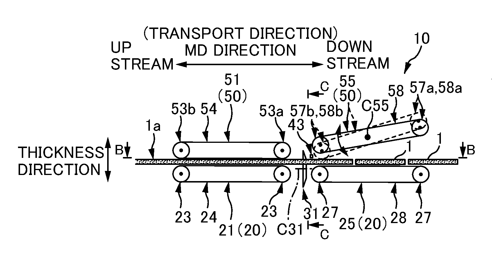
[0164]FIG. 10A is a schematic side view of a cutting apparatus 10a of a second embodiment, FIG. 10B is a view along arrows B-B in FIG. 10A, and FIG. 10C is a view along arrows C-C in FIG. 10A.

[0165]The second embodiment is different from the first embodiment mainly in that the movement direction of the rotatable blade 31 in the cutting apparatus 10a is not along the CD direction but along the thickness direction of the semi-finished product 1a (corresponding to an intersecting direction). Portions other than the above are substantially similar to those in the first embodiment. Accordingly, in the description below, the same sign is used for the same configurations as the first embodiment, and description thereof is omitted.

[0166]During a transport suspension of the semi-finished product 1a, the rotatable blade 31 in the cutting apparatus 10a moves from the one side to the other side in the thickness direction of the semi-finished product 1a or moves from the other side to the one si...


PUM

PropertyMeasurementUnit
Thicknessaaaaaaaaaa
Widthaaaaaaaaaa
Distanceaaaaaaaaaa

Abstract

A web-member cutting apparatus for cutting a web member at intervals in a transport direction includes: an intermittent transport mechanism for intermittently transporting the web member in the transport direction; a disc-like rotatable blade member for cutting the web member by moving along an intersecting direction while rotating about a rotation shaft during a suspension period of transport of the web member, and a downstream pressing member for regulating movement of the web member by pressing the web member against the intermittent transport mechanism at a position downstream from a target cut position in the transport direction throughout a period during which the rotatable blade member is cutting the web member.

Description

CROSS-REFERENCE TO RELATED APPLICATIONS[0001]The present application claims priority from Japanese Patent Application No. 2012-115783 filed on May 21, 2012, which are herein incorporated by reference.BACKGROUND[0002]1. Technical Field[0003]The present invention relates to an apparatus and a method for cutting a web member that has a plurality of fibers including tows.[0004]2. Related Art[0005]A conventional cleaning web member is known into which a handle member is inserted to make the web member usable for cleaning of a tabletop and the like (JP 2005-40641A). Such a cleaning web member has a main body in which a plurality of fibers are layered on a base sheet. As the fibers, used are thermoplastic fibers, called tows.[0006]In the production line of the cleaning web member, a plurality of tows whose fiber direction is in a transport direction are secured by means such as welding to a base sheet that is continuous along the transport direction. Thus, a web member that is continuous i...

Claims


Application Information

Patent Timeline
IPC IPC(8): B26D7/32B26D7/01
CPCB26D7/32B26D7/015B26D7/025B26D7/04B26D7/0625B26D7/14B26D1/18Y10T83/4645Y10T83/04Y10T83/0605Y10T83/4594Y10T83/7763
Inventor NOBUKUNI, HISAOKI
Owner UNI CHARM CORP
Why Eureka
Try Eureka