Supercharge Your Innovation With Domain-Expert AI Agents!

In-line pretreatment system for machine parts

a pretreatment system and machine parts technology, applied in the direction of cleaning process and equipment, chemistry apparatus and processes, cleaning using liquids, etc., can solve the problems of inability to achieve substantial added cost, considerable expense, and sacrifice soak time or, alternatively, add length to the washer

Active Publication Date: 2013-11-21
PEM
View PDF10 Cites 2 Cited by
  • Summary
  • Abstract
  • Description
  • Claims
  • Application Information

AI Technical Summary

Benefits of technology

The invention is a device used to clean machine parts before they are painted or powder coated. The device consists of a series of wash stages, each containing a tank with a pump and L-shaped uprights holding plastic shrouds. The cleaning liquid is pumped from the tank to the parts through the headers and risers. The device helps to improve the cleaning process and ensures machine parts are ready for further treatment.

Problems solved by technology

Over time, should the company decide to increase the conveyor speed to add throughput, it would have to sacrifice soak time or, alternatively, add length to the washer, usually at considerable expense.
Also, if the company needs to add another stage to improve its process or possibly add another type of process, it will not be able to do that without substantial added cost.
Existing washers of which we are aware typically occupy a significant amount of factory floor space and are inefficient in terms of energy needed to pump and heat the liquid cleaning agents.
Another problem with prior art parts washer booths is that they do not permit easy access to the piping system comprising the nozzles, risers and headers contained within the booth so that adjustments may be made to the direction and spray pattern employed.
Another drawback of prior art washers is that they need some type of filtration system in the first wash stage to help keep the bath clean so as to offer an extended bath life.
Such filtration systems therefore require additional energy and floor space.

Method used


Image

  • In-line pretreatment system for machine parts
  • In-line pretreatment system for machine parts
  • In-line pretreatment system for machine parts

Examples


Embodiment Construction

[0033]This description of the preferred embodiments is intended to be read in connection with the accompanying drawings, which are to be considered part of the entire written description of this invention. In the description, relative terms such as “lower”, “upper”, “horizontal”, “vertical”, “above”, “below”, “up”, “down”, “top” and “bottom” as well as derivatives thereof (e.g., “horizontally”, “downwardly”, “upwardly”, etc.) should be construed to refer to the orientation as then described or as shown in the drawings under discussion. These relative terms are for convenience of description and do not require that the apparatus be constructed or operated in a particular orientation. Terms such as “connected”, “connecting”, “attached”, “attaching”, “join” and “joining” are used interchangeably and refer to one structure or surface being secured to another structure or surface or integrally fabricated in one piece, unless expressively described otherwise.

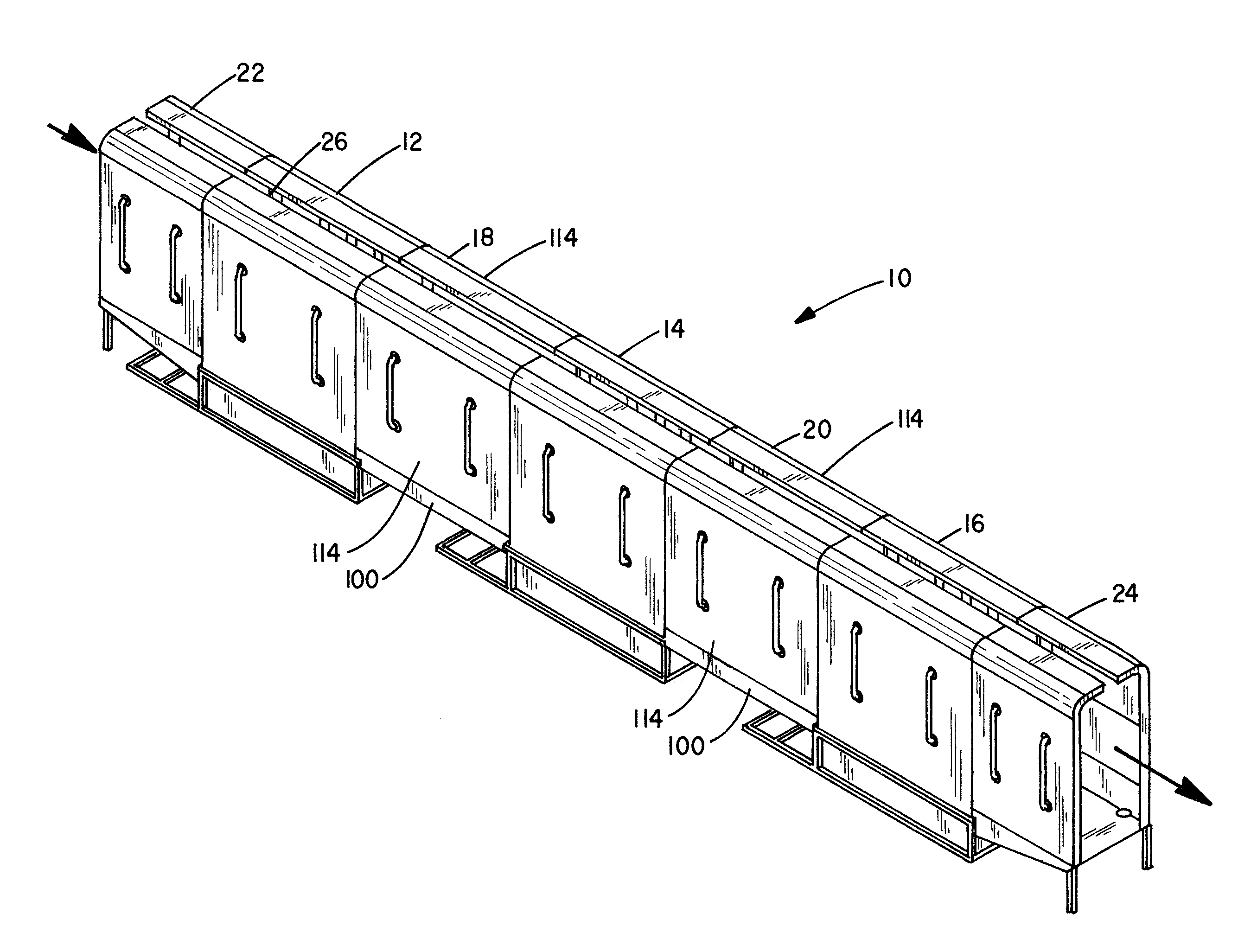
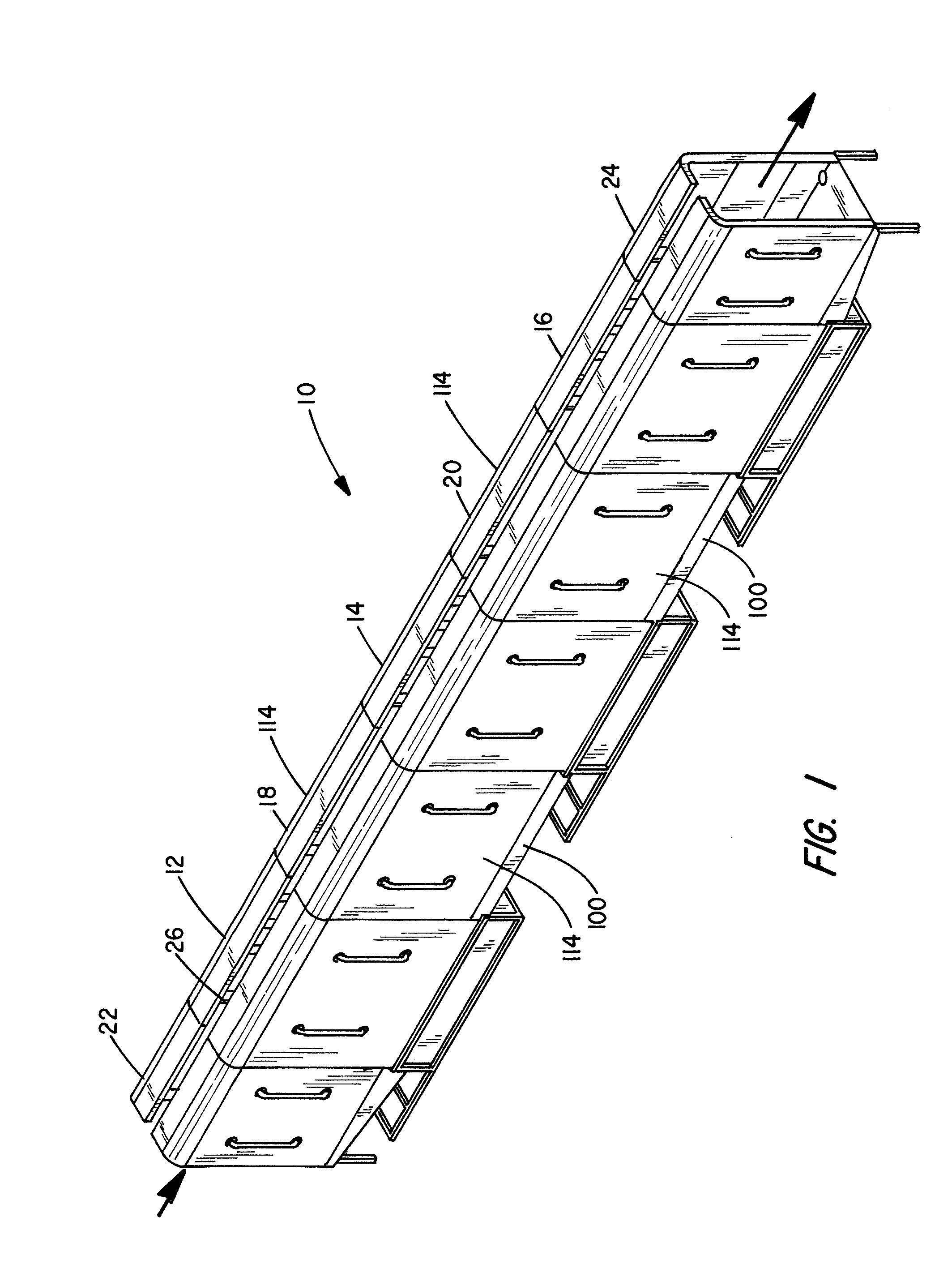
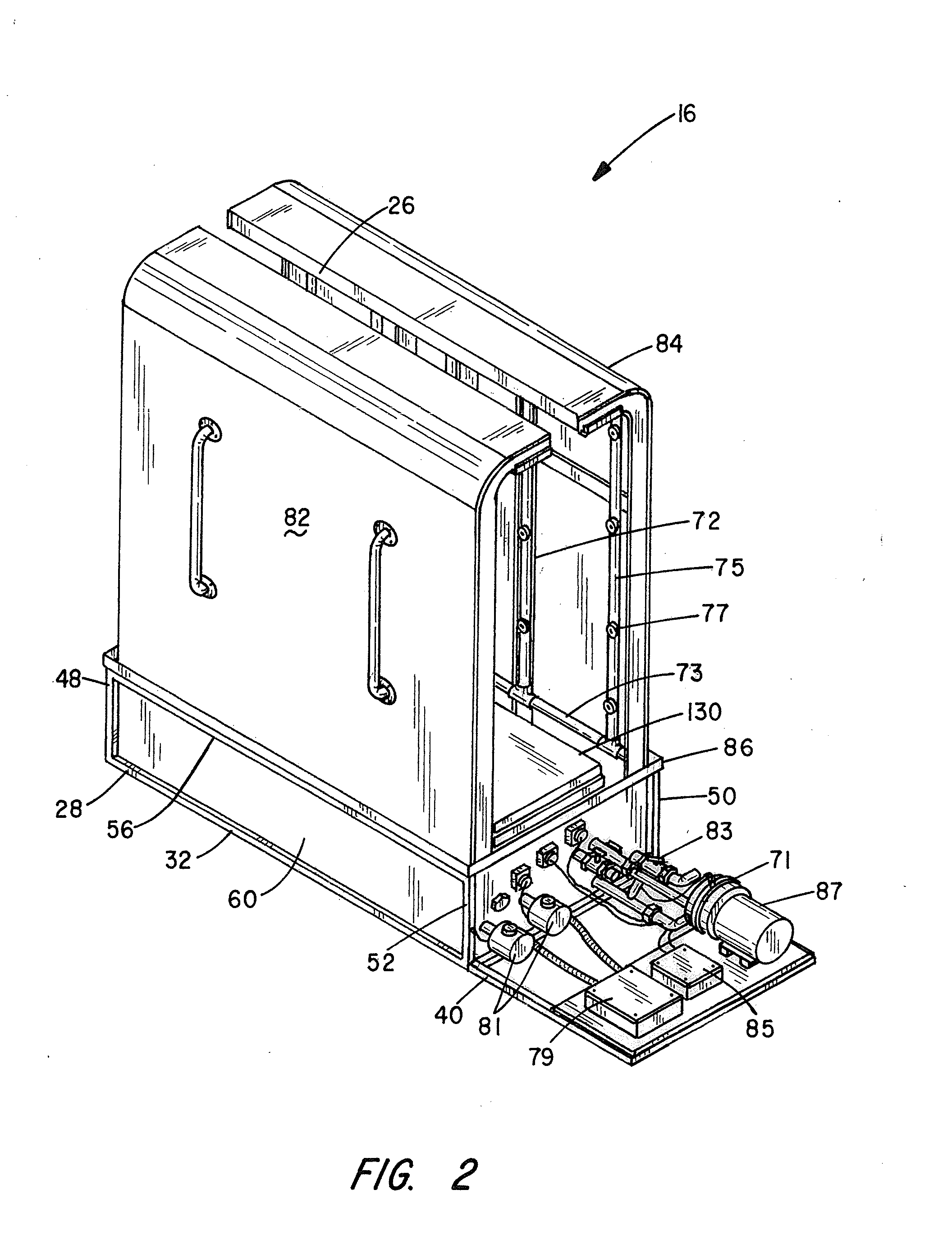
[0034]Referring first to FIG. ...


PUM


Abstract

An in-line parts washing system comprising concatenated modules of two discrete lengths where certain of the modules have a self-contained tank of parts cleaning chemical along with a motor-driven pump for forcing the cleaning chemical through spray heads enclosed in a shroud through which the parts to be cleaned are transported via a conveyor. Other modules disposed in-line with the wash modules provide zones where the cleaning chemical dripping from the parts is collected and redirected back into the tanks from which it originated. The ability to swap modules of differing length allows a user to easily alter the cleaning process.

Description

BACKGROUND OF THE INVENTION[0001]I. Field of the Invention[0002]This invention relates generally to apparatus for industrial pre-cleaning of machine parts prior to painting or powder coating of such parts, and more particularly to a multi-stage, in-line washer whereby parts to be cleaned are subjected to a pressurized spray at elevated temperatures of chemical cleaning solutions for predetermined time periods determined by the number of stages employed.[0003]II. Discussion of the Prior Art[0004]As explained in the Pascaru U.S. Pat. No. 5,257,739, machined parts must be chemically cleaned to remove oils and other residues therefrom before painting or powder coating operations can be performed on these parts. Spraying equipment used to clean, rinse and otherwise treat articles of manufacture take place in a confined area, such as a spray or washer booth, in which various liquids are piped under pressure through headers into a plurality of vertical pipes, called risers, that connect to...

Claims


Application Information

Patent Timeline
Patent Type & Authority Applications(United States)
IPC IPC(8): B08B3/02B08B3/08B08B3/04
CPCB08B3/022B05B16/90B05B16/40B05B16/80B08B3/041
Inventor KAPSNER, JOHN GREGORYSCHREYER, THEODORE LOWELLMCCABE, KELLY GORDON
Owner PEM
Features
  • R&D
  • Intellectual Property
  • Life Sciences
  • Materials
  • Tech Scout
  • Unparalleled Data Quality
  • Higher Quality Content
  • 60% Fewer Hallucinations
Learn More