
Optically Readable Identification Security Tag or Stamp

Inactive Publication Date: 2013-11-21
FREEMAN JAMES
View PDF29 Cites 30 Cited by
  • Summary
  • Abstract
  • Description
  • Claims
  • Application Information

AI Technical Summary

Benefits of technology

The present invention is about a new and unique security tag or stamp design that has several features. The tag is made by positioning a large number of small 3-D objects in a regular pattern on a base substrate, which creates a unique code that cannot be easily copied or counterfeited. The invention involves using a base substrate with receptors or arrangements to hold the objects, which can be in a separate section to increase the level of uniqueness. The security tag is optical or x-ray scannable and does not require a large number of randomly chosen objects. The information encoded in the tag is machine or optically readable by a computer and cannot be copied or counterfeited. The invention is suitable for use on documents such as passports, identification cards, and critical military components that need audit trails or could be subject to counterfeiting.

Problems solved by technology

Counterfeit replacement spare parts and forgery of sensitive documents and paper currencies have been a severe and on-going problem for a long time.
The opening sentences of the article read: “The American military faces a growing threat of potentially fatal equipment failure—and even foreign espionage—because of counterfeit computer components used in warplanes, ships and communication networks.
Security tags and identifiers to help prevent counterfeiting are well known but have two principal flaws that limit their utility.
Two-dimensional (“2-D”) printed tags are susceptible to copying or printing and existing security tags having three-dimensional (“3-D”) features suffer from the difficulty of verifying that the 3-D pattern is in fact the “right” pattern, the pattern which was originally created on the item when it was fabricated.
Additionally, since the image is comprised of analog data, comparison to the expected pattern is difficult, requiring pattern-recognition software and computation.
The random occurrence of the colors of the objects in the regular grid locations create unique and practically impossible to duplicate tags.
However, such prior efforts have not been overly successful.
None of the prior art can be combined in this way to suggest these necessary modifications.
There is no teaching, suggestion, or motivation that would have enabled a person of ordinary skill in the art to modify any prior art security or identification tags.

Method used


Image

  • Optically Readable Identification Security Tag or Stamp
  • Optically Readable Identification Security Tag or Stamp
  • Optically Readable Identification Security Tag or Stamp

Examples


first embodiment

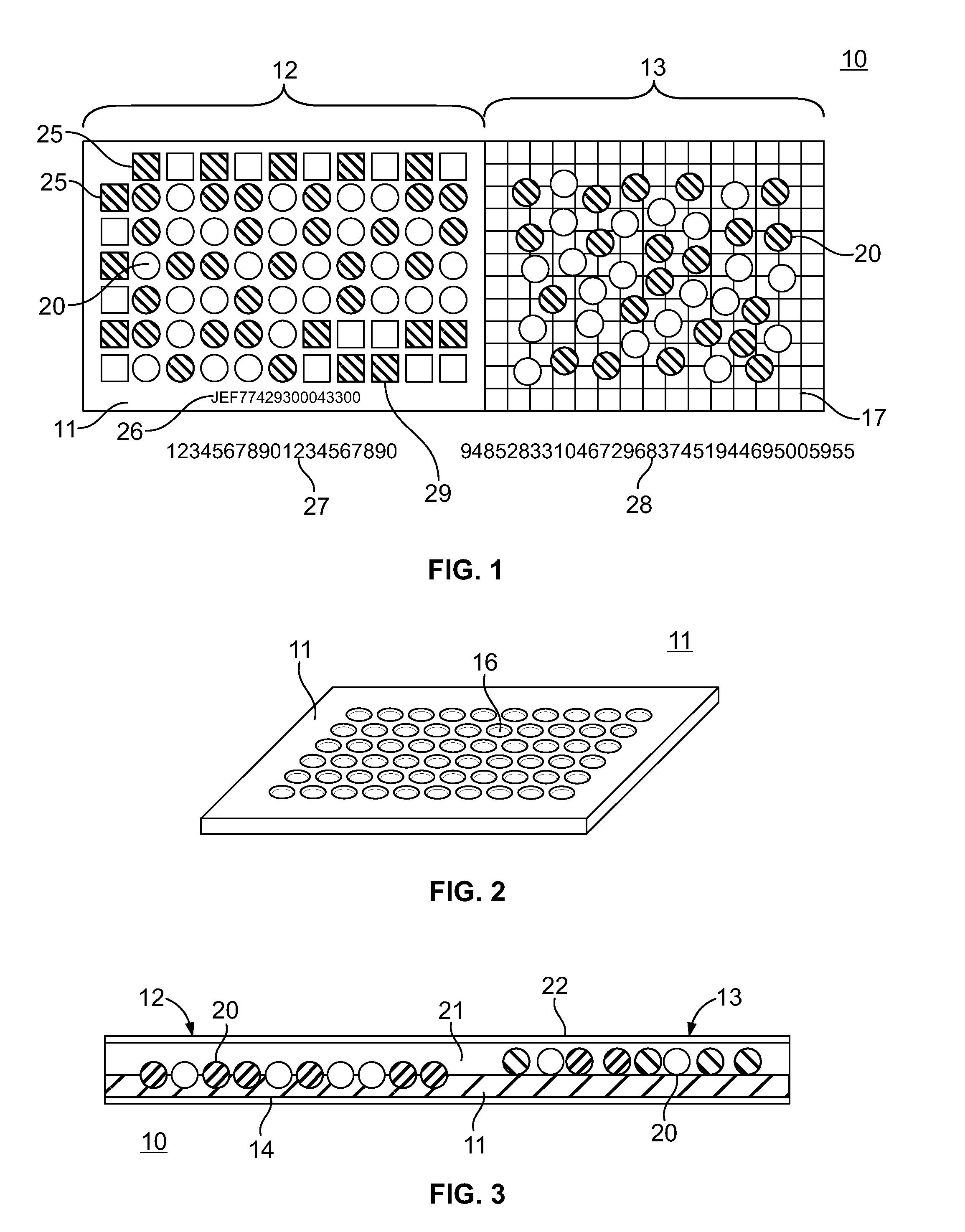
[0053]Referring to FIG. 1, the security tag 10 comprises two major components—a suitable base substrate 11 and a substantial amount, preferably in the range of thousands or more, of objects 20 suitably supported and positioned on or in such substrate 11. Objects 20 are of at least two structural configurations, such as of at least two different colors, at least two different hardnesses or at least two different x-ray emission qualities. As shown in FIG. 1, substrate 11 is divided into a first section 12 shown on the left side and a second section 13 shown on the right side of FIG. 1. The first embodiment described herein refers to section 12 shown on the left side of FIG. 1.

[0054]Round objects 20, as described in detail below, are randomly distributed in section 12 of substrate 11 in a substantially predetermined regular geometrical pattern or patterns, such as straight horizontal rows and vertical columns, which may be parallel. The random distribution of objects 20 and the differe...

second embodiment

[0064]Referring again to FIGS. 1 and 3, security tag 10 of the present invention comprises an additional plurality of 3-D objects 20 randomly distributed on the separate, substantially flat surface of second section 13 of substrate 11. Section 13 of substrate 11 is located on the right side of substrate 11 remote from section 12 as viewed in FIGS. 1 and 3. 3-D objects 20 positioned directly on a substantially flat section of substrate 11 are suitably encapsulated in layer 21 of a suitable, preferably transparent, compound. Random distribution of colors of such objects 20 on section 13 of substrate 11 provides for coding of additional unique, readily readable information on security tag 10.

[0065]3-D objects 20 distributed directly on a separate, substantially flat section 13 of substrate 11 may be of just one suitable color, while substrate 11 may be of another suitable color. Random distribution of any suitable number of such objects 20 of one color directly on substrate 11 made of ...


PUM


Abstract

The invention relates to a security tag made unique by randomly distributing a mixture of large numbers of multicolored small objects, such as two colored glass balls, into a regular geometric array or pattern onto a substrate and encapsulating those objects. The objects in the regular array on the substrate will create a unique, non-reproducible pattern. The data, saved to a secure database, can be processed and calculated quantities can be derived from the field of binary data, which can be affixed to the document or manufactured part that the stamp is affixed to. The regular array can be read out by scanner, quantities calculated, and compared to the values printed on the part or document. Additionally, the regular array can be read out by optical scanner and parts or all of the data compared to the data stored in the secure database.

Description

[0001]This application claims priority to and is a continuation-in-part of non-provisional patent application Ser. No. 13 / 271,441 filed Oct. 12, 2011 to the extent allowed by law.BACKGROUND OF THE INVENTION[0002]1. Field of the Invention[0003]The present invention is in the field of product or document marking or identification. In particular, this invention relates to unique product identification and protection against counterfeiting.[0004]2. Description of the Prior Art[0005]Counterfeit replacement spare parts and forgery of sensitive documents and paper currencies have been a severe and on-going problem for a long time. Whole sectors of the world economy, such as government defense sectors, are overrun by counterfeiters. The most affected sectors are the clothing, fashion, music, movie and software industries, which is flooded with false CDs and DVDs. The victims are legitimate industries and consumers, predominantly in developed economies. The losses are in the hundreds of bill...

Claims


Application Information

Patent Timeline
IPC IPC(8): G06K19/06
CPCG06K19/06037B42D25/00B42D25/387B42D25/45B42D2033/04B42D2033/20B42D2035/14G03G21/043G06K19/0614
Inventor FREEMAN, JAMES
Owner FREEMAN JAMES
Learn More