
Capacitive touch panel device

a touch panel and capacitive technology, applied in the field of capacitive touch panel devices, can solve the problem of limited number of i/o of touch driver/controllers, and achieve the effect of increasing the accuracy performance of the touch panel

Inactive Publication Date: 2013-11-21
INNOCOM TECH SHENZHEN +1
View PDF8 Cites 14 Cited by
  • Summary
  • Abstract
  • Description
  • Claims
  • Application Information

AI Technical Summary

Benefits of technology

The invention aims to improve the accuracy of touch panels with a fixed layout. This is achieved by adding more sensors and calculating the touch position using a dedicated algorithm. This reduces the effect of the "dead area" of a touch sensor and improves accuracy, especially for small touch input areas.

Problems solved by technology

For various reasons, such as costs, design and process capability (track / gap capabilities) and display form factor (e.g. availability for track / routing layout) the number of I / O of the touch driver / controller will be limited.

Method used


Image

  • Capacitive touch panel device
  • Capacitive touch panel device
  • Capacitive touch panel device

Examples


Embodiment Construction

[0035]First, coplanar touch panels will be described in some more detail.

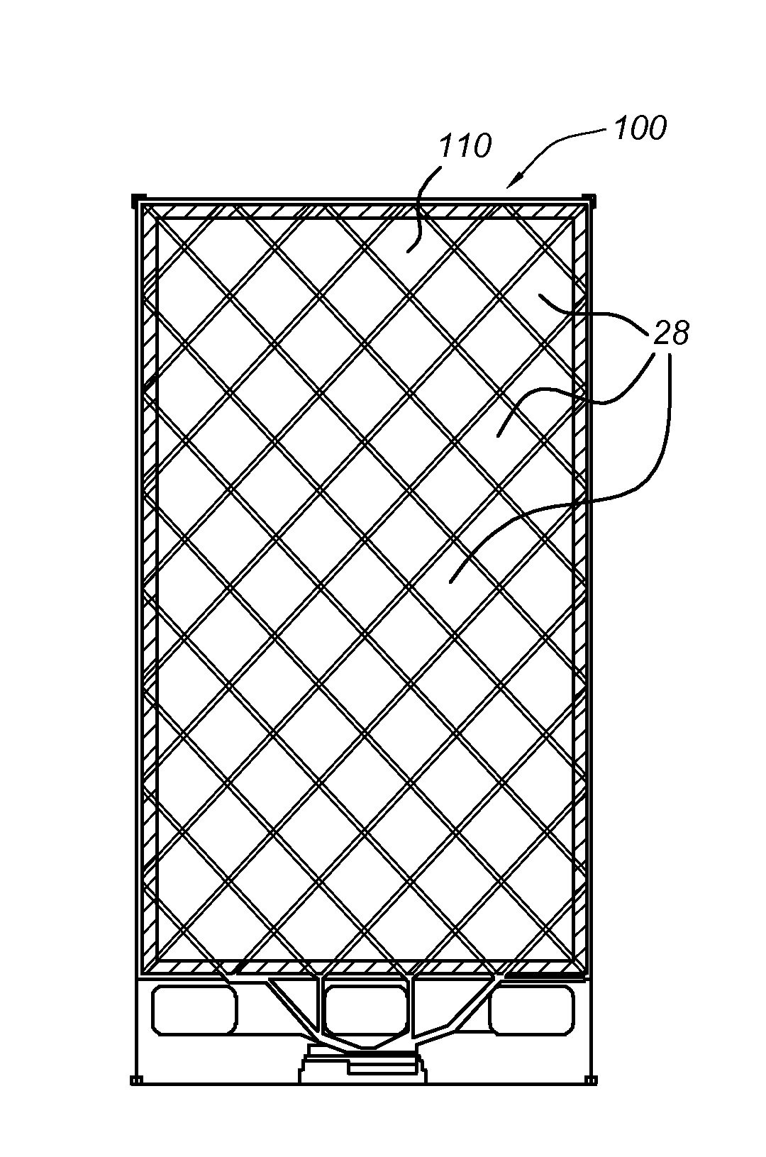
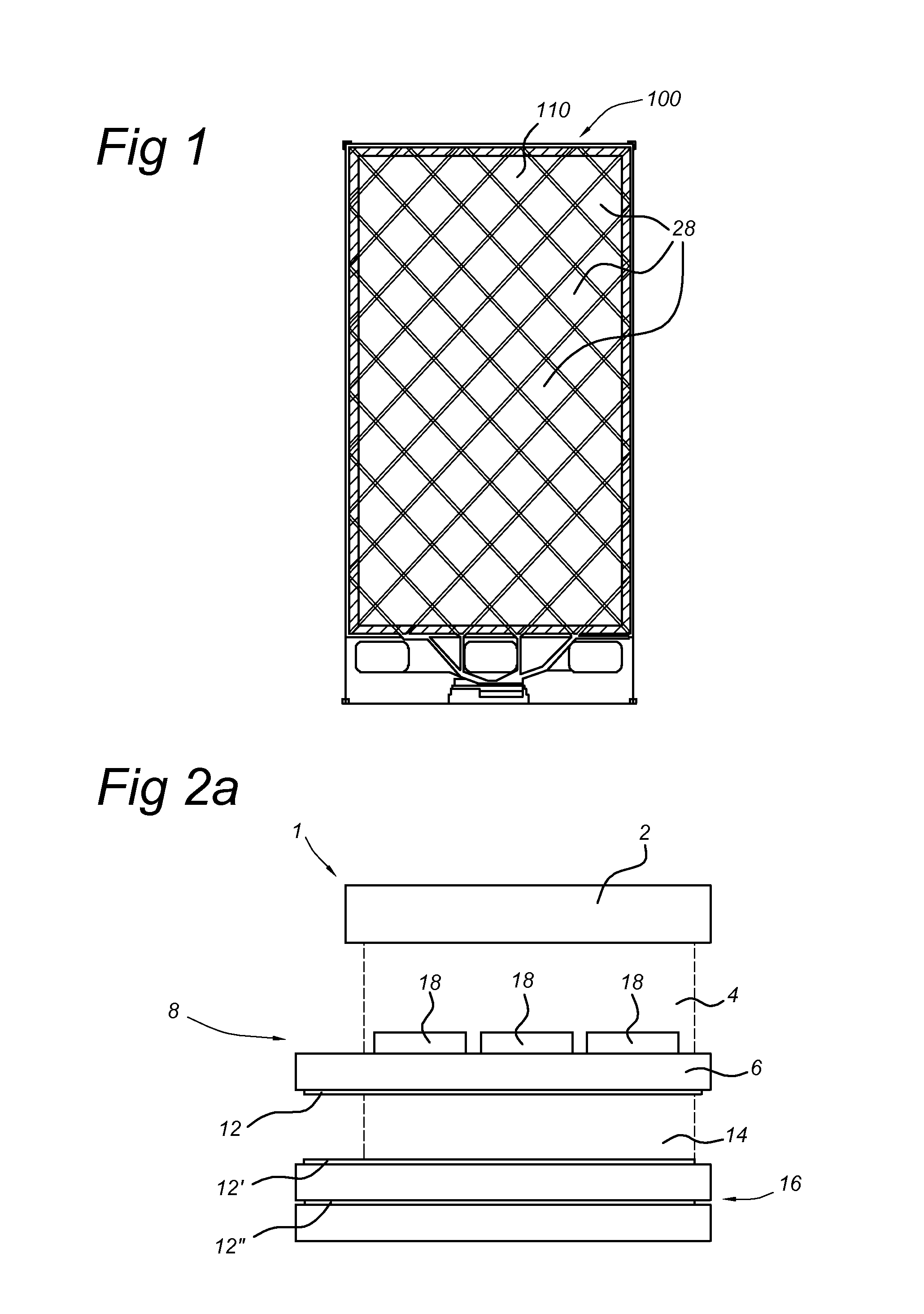
[0036]FIG. 1 schematically shows a top view of an electronic device 100 comprising a coplanar capacitive touch panel device. Examples of applications with such devices are mobile telephones, tablet computers and other portable devices. In addition, display-less (input) devices such as mouse pads and graphics tablets. The touch panel surface 110 of the electronic device 100 can be optimized for finger touches and stylus touches.

[0037]The touch panel surface 110 is divided in a number of touch sensors 28. In the example of FIG. 1 the sensors 28 form a diamond pattern, but other patterns are possible as well. Each sensor 28 comprises a touch sensing element 18 (not shown in FIG. 1) which can be independently read by a processor (not shown).

[0038]The touch panel surface 110 is typically protected by a glass cover layer. For electronics devices comprising a display 16, the display is typically provided underneath th...


PUM


Abstract

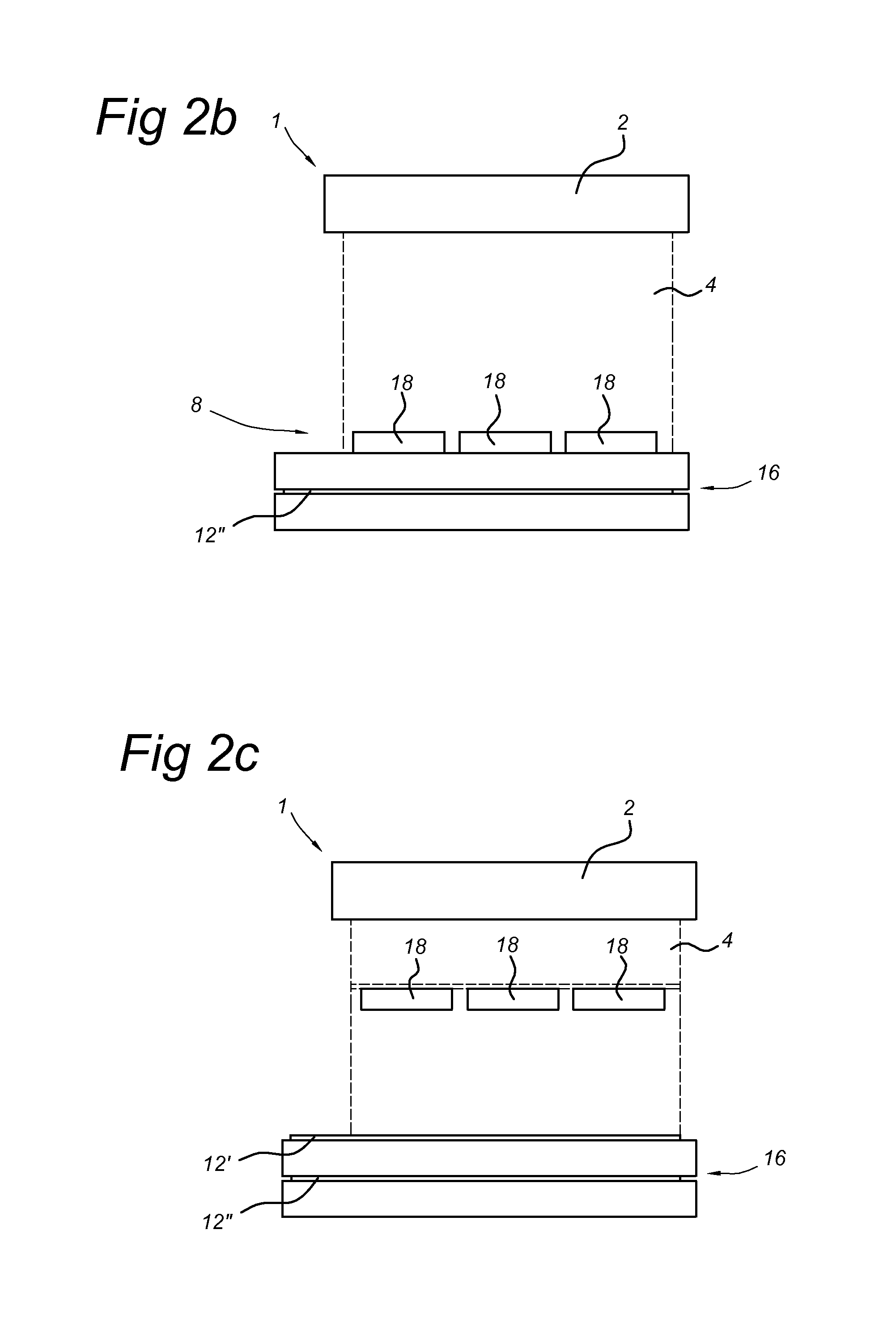
The invention provides a touch panel device comprising, and arranged above each other in a downward direction, a cover layer for use as a touch surface, a sensor layer comprising a plurality of sensing elements, the sensing elements being arranged to register capacitance, characterized in that between the cover layer and the sensor layer is an electrically-resistive layer, electrically resistive layer being a electrically non-insulating layer and having an electrical resistance is provided, wherein the electrical resistance of the electrically-resistive layer is lower than the electrical resistance of the cover layer and higher than the electrical resistance of the sensing elements. The electrically-resistive layer can have a resistance suitable for causing, in response to a touch event above a center of a central sensing element, a detectable change in the capacitance as measured by at least two sensing elements adjacent to the central sensing element.

Description

FIELD OF THE INVENTION[0001]The invention relates to capacitive touch panel devices. The invention further relates to a method for determining a touch location on a capacitive touch panel device, and to an electronic apparatus comprising a display and a touch panel device.BACKGROUND OF THE INVENTION[0002]Capacitive touch panel devices are widely used to allow user interaction with electronic devices. In particular, a transparent touch panel can be used on top of a display device to allow a user to interact with the electronic device via a graphical user interface presented on the display device. Such touch panels are used in for example mobile phones, tablet computers, and other portable devices.[0003]A known touch panel for use with such devices comprises a glass plate provided with a first electrode comprising a plurality of first sensing elements on one face of the glass plate, and a second electrode on an opposite face of the glass plate. The core operating principle is that the...

Claims


Application Information

Patent Timeline
IPC IPC(8): G06F3/044
CPCG06F3/044G06F3/0445G06F3/0446G06F3/0412
Inventor VERWEG, FRANSTOUSSAINT, SERGEYEATES, DAVID
Owner INNOCOM TECH SHENZHEN
Learn More