
Circuit for sensing multi-level cell

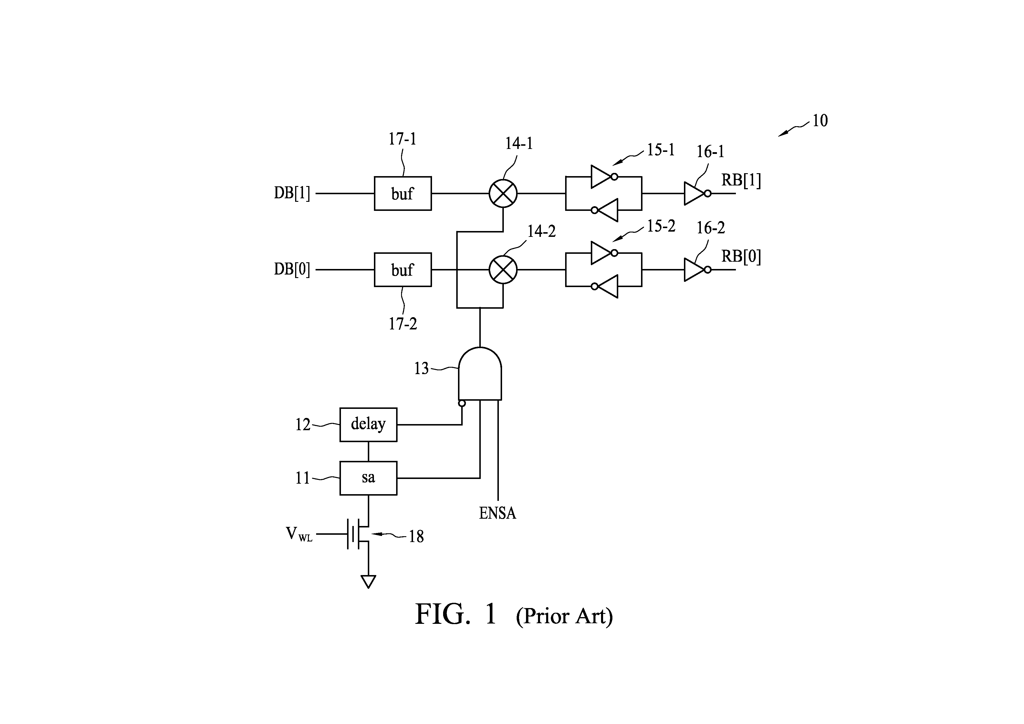
a multi-level cell and sensing circuit technology, applied in the field of sensing memory cells, can solve the problems of large chip area, large read margin issue of sensing circuit b>10/b>, and not desired

Active Publication Date: 2013-11-21
ELITE SEMICON MEMORY TECH INC
View PDF2 Cites 0 Cited by
  • Summary
  • Abstract
  • Description
  • Claims
  • Application Information

AI Technical Summary

Benefits of technology

The present invention provides a circuit for sensing a multi-level cell (MLC) that includes a first switch, a second switch, a first switch control unit, and a second switch control unit. The first switch control unit controls the first switch based on a first data bit from a counter, while the second switch control unit controls the second switch based on a second data bit from the counter. Additionally, the circuit includes a first sense amplifier coupled to the first switch and a first switch control unit to control the first switch so as to allow an output from the first sense amplifier to override the first read bit in response to the first data bit from the counter.

Problems solved by technology

The sensing circuit 10 may suffer a read margin issue due to a relatively small signal width of a switch turn-on signal.
Furthermore, the buffers 17-1 and 17-2 may consume a large chip area and thus are not desired.

Method used


Image

  • Circuit for sensing multi-level cell
  • Circuit for sensing multi-level cell
  • Circuit for sensing multi-level cell

Examples


Embodiment Construction

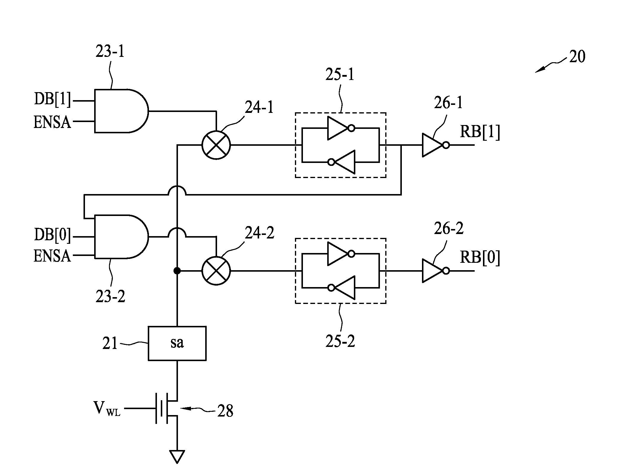
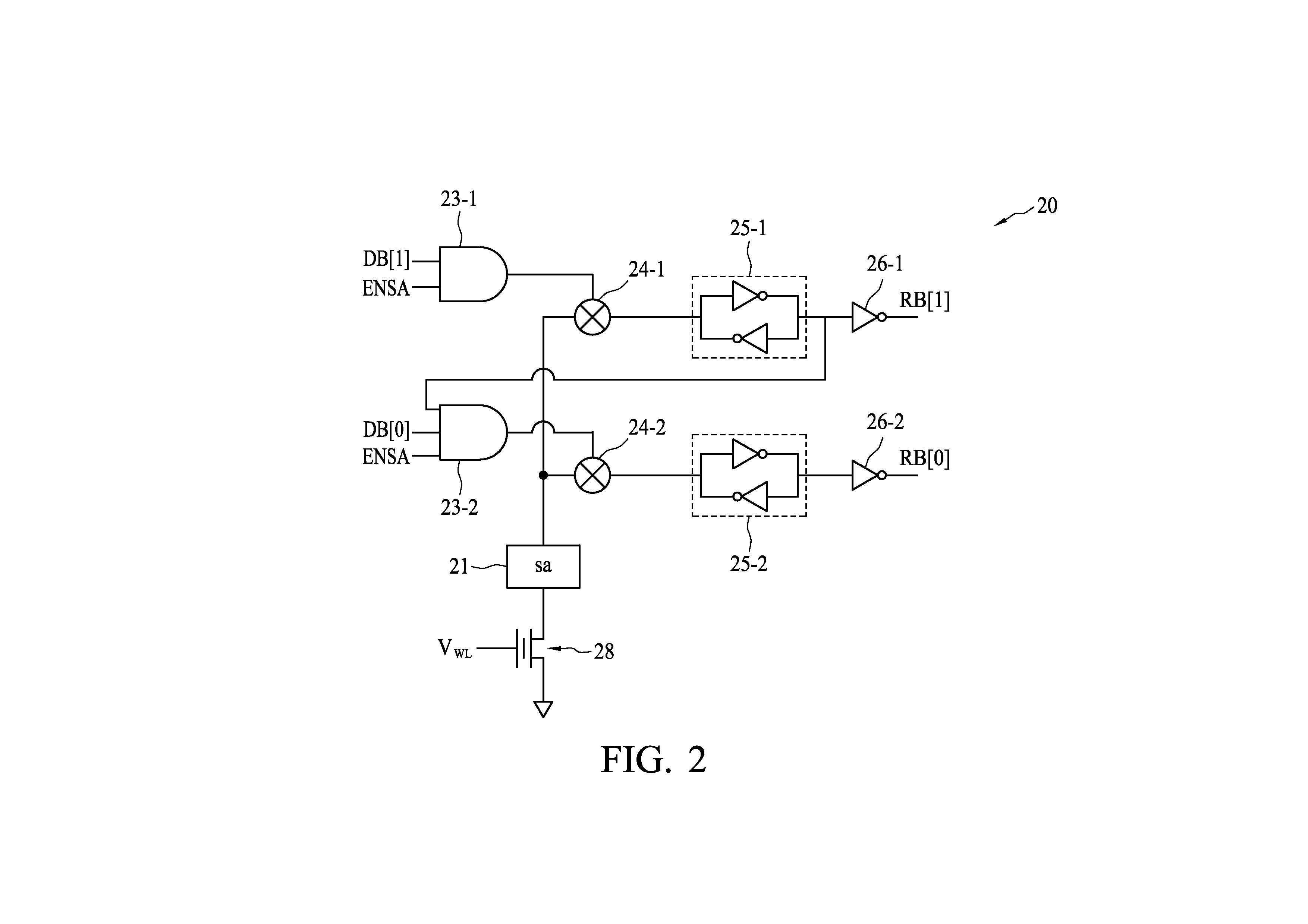
[0015]FIG. 2 is a circuit diagram of a circuit 20 for sensing an MLC in accordance with one embodiment of the present invention. Referring to FIG. 2, the circuit 20 may include a sense amplifier 21, a first switch 24-1, a second switch 24-2, a first switch control unit 23-1 and a second switch control unit 23-2.

[0016]The sense amplifier 21 includes an output coupled to the first and second switches 24-1 and 24-2. Moreover, the sense amplifier 21 compares a threshold voltage of an MLC 28 with a sensing voltage V. The MLC 28, capable of storing more than one bit of information, has several possible states. In the present embodiment, the MLC 28 is able to store 2 bits of information and thus has four possible states. Accordingly, the sensing voltage V may have three different voltage levels for sensing the MLC 28 that stores one of four threshold voltages. In one embodiment, the sensing voltage V may be applied in order of voltage levels from low to high during a sensing period. As an ...


PUM


Abstract

A circuit for sensing a multi-level cell (MLC) comprises a first switch associated with a first read bit, a second switch associated with a second read bit, a first switch control unit to control the first switch in response to a first data bit from a counter, and a second switch control unit to control the second switch in response to a second data bit from the counter.

Description

BACKGROUND OF THE INVENTION[0001]1. Field of the Invention[0002]The present invention generally relates to a circuit for sensing a memory cell and, more particularly, to a circuit for sensing a multi-level cell.[0003]2. Description of the Related Art[0004]A multi-level cell (MLC) refers to one having a plurality of threshold voltages. To sense an MLC, a sensing circuit may traditionally employ an output signal from a sense amplifier to control the on / off state of a switch in order to decide whether to read data bits from a counter.[0005]FIG. 1 is an exemplary circuit diagram of a sensing circuit 10 for sensing an MLC in prior art. Referring to FIG. 1, the sensing circuit 10 may include a sense amplifier 11, a delay unit 12, a logic “AND” gate 13, a first switch 14-1 and a second switch 14-2.[0006]The sense amplifier 11 compares a threshold voltage of an MLC 18 with a word line voltage V. If the threshold voltage is smaller than VWL, the sense amplifier 11 provides a signal of logic ...

Claims


Application Information

Patent Timeline
Patent Type & Authority Applications(United States)
IPC IPC(8): G11C7/06
CPCG11C11/5642G11C2211/5642G11C2211/5644
Inventor TSAI, CHENG-HUNG
Owner ELITE SEMICON MEMORY TECH INC
Features
  • Generate Ideas
  • Intellectual Property
  • Life Sciences
  • Materials
  • Tech Scout
  • Unparalleled Data Quality
  • Higher Quality Content
  • 60% Fewer Hallucinations
Learn More