
Distributed and dynamical brillouin sensing in optical fibers

a dynamic and optical fiber technology, applied in the direction of converting sensor output, reflectingometers using simulated back-scatter, testing fibre optic/optical waveguide devices, etc., can solve the problem of a fair amount of slow procedur

Inactive Publication Date: 2013-11-21
RAMOT AT TEL AVIV UNIV LTD
View PDF12 Cites 31 Cited by
  • Summary
  • Abstract
  • Description
  • Claims
  • Application Information

AI Technical Summary

Benefits of technology

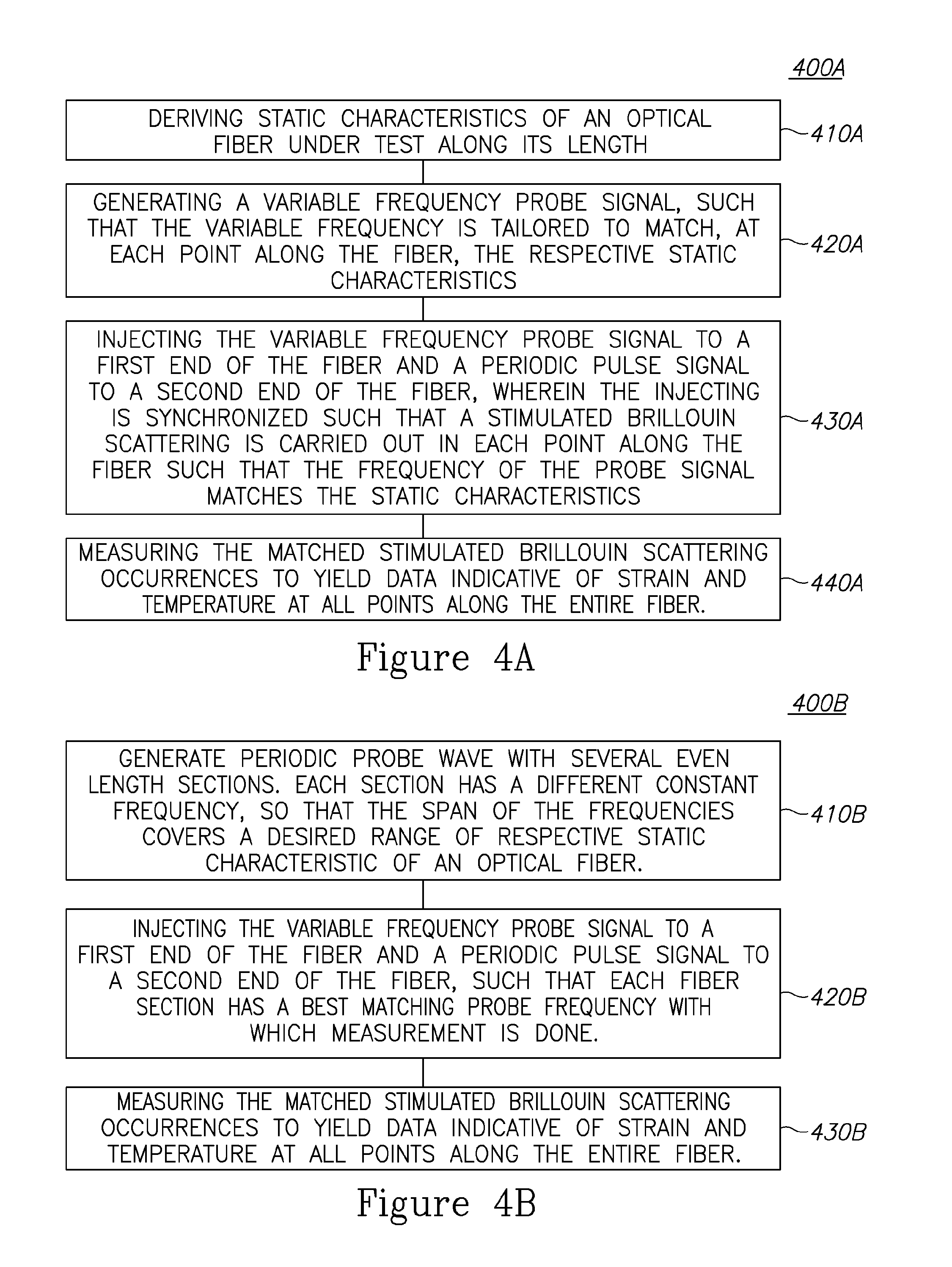
The present invention provides a method to measure strain along an entire optical fiber using stimulated Brillouin scattering (SBS). The method uses a specially synthesized and adaptable probe wave that always works on the slope of the local BGS, allowing a single pump pulse to sample fast strain variations along the entire fiber. This allows for the simultaneous distributed measurement of dynamic strain along the entire fiber, with different average strain characteristics at different locations. The method uses an average characteristic of the fiber to generate a probe signal, which is synchronized with the pump pulse wave to ensure optimal conditions for SBS at each location. The periodicity of the probe wave allows for the measurement of strain / temperature within a certain range and granularity. The method has a high strain resolution and can measure strain variations on the order of KHz.

Problems solved by technology

To achieve high strain / temperature resolution over a wide dynamic range of these two measurands, the scanned frequency range must be wide (>100 MHz) and of high granularity, resulting in a fairly slow procedure, that often requires multiple scanning to reduce noise.

Method used


Image

  • Distributed and dynamical brillouin sensing in optical fibers
  • Distributed and dynamical brillouin sensing in optical fibers
  • Distributed and dynamical brillouin sensing in optical fibers

Examples


Embodiment Construction

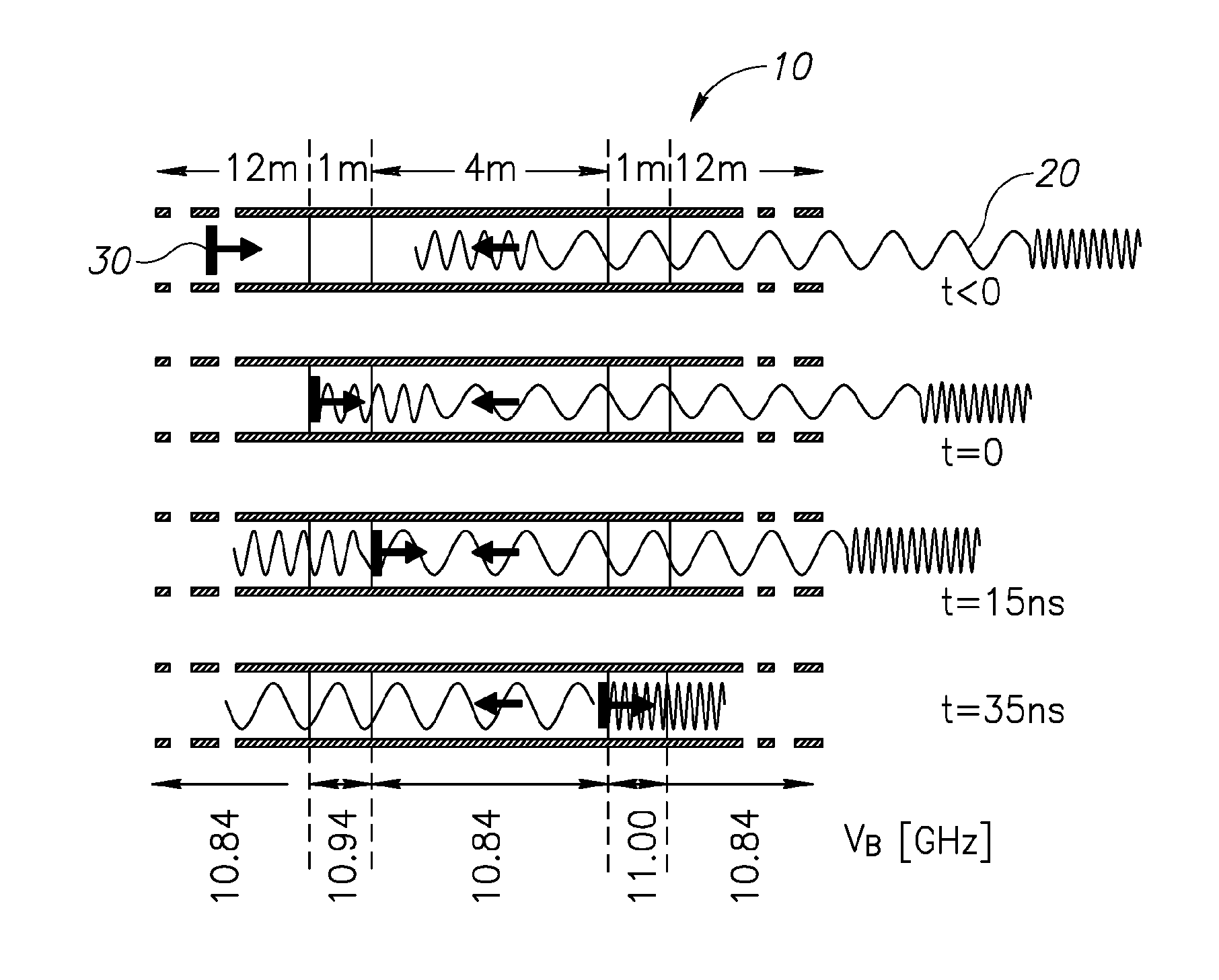
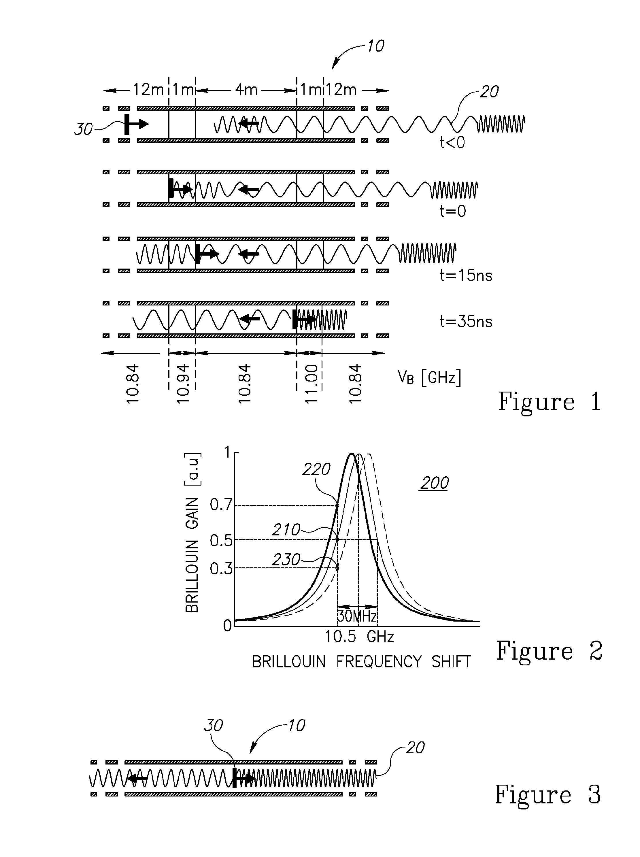
[0022]The present invention, in embodiments thereof, suggests using a probe signal with variable frequency tailored to match average characteristics of an optical fiber under test. Under average strain / temperature conditions, the Brillouin gain spectrum of a uniform fiber is constant along the entire length of the fiber under test. For a given pump frequency, the optical frequency of the counter-propagating probe is then chosen to coincide with one of the −3 dB points of the ˜30 MHz-wide Lorentzian Brillouin gain spectrum. Alternatively, any other point along the slope may be chosen, possibly but not necessarily the center of the slope. It is understood that in the following description, any reference to a −3 dB point should be interpreted as a point along the slope.

[0023]In the presence of strain changes, the BGS shifts at approximately 50 MHz / 1000 μS, and the fixed frequency probe wave will now experience less or more Brillouin gain, depending of the direction of the BGS shift. Ea...


PUM

PropertyMeasurementUnit
lengthaaaaaaaaaa
lengthaaaaaaaaaa
frequenciesaaaaaaaaaa

Abstract

A method of distributed and dynamical Brillouin sensing in optical fibers is provided herein. The method includes the following stages: deriving average characteristics of an optical fiber along its length; generating a variable frequency probe signal, such that the variable frequency is tailored to match, at specified points along the fiber, the respective average characteristics; injecting the variable frequency probe signal to a first end of the optical fiber and a periodic pulse signal to a second end of the optical fiber, wherein the injecting is synchronized such that a stimulated Brillouin scattering is carried out at each one of the specified points along the optical fiber, such that a frequency difference between the probe signal and the pump signal matches the average characteristics of the fiber; and measuring occurrences of the stimulated Brillouin scattering, to yield data indicative of strain and temperature at all points along the optical fiber.

Description

BACKGROUND[0001]1. Technical Field[0002]The present invention relates to sensing Brillouin scattering in optical fibers and more particularly, to a distributed and dynamical Brillouin sensing.[0003]2. Discussion of the Related Art[0004]The use of stimulated Brillouin scattering (SBS) for fiber optic strain and temperature distributed sensors is well known in the art. One of the most widely used approaches is the classical method of Brillouin optical time-domain analysis technique (BOTDA), where a pump pulse interacts with a counter propagating probe wave. Strain and temperature information is deduced from the local Brillouin gain spectrum (BGS), which is measured by scanning the optical frequency of the probe wave.[0005]To achieve high strain / temperature resolution over a wide dynamic range of these two measurands, the scanned frequency range must be wide (>100 MHz) and of high granularity, resulting in a fairly slow procedure, that often requires multiple scanning to reduce nois...

Claims


Application Information

Patent Timeline
Patent Type & Authority Applications(United States)
IPC IPC(8): G01K11/32
CPCG01K11/32G01D5/35303G01D5/35364G01L1/242G01M11/319G01M11/39G01K11/322
Inventor TUR, MOSHEPELED, YAIR
Owner RAMOT AT TEL AVIV UNIV LTD
Learn More