Centrifugal separator and an outlet element for a centrifugal separator

a centrifugal separator and outlet element technology, applied in centrifuges, rotary centrifuges, etc., can solve the problems of limit to the range of radial distance from the axis, limit to the adjustment range of the outlet housing,

Active Publication Date: 2013-11-21
ALFA LAVAL CORP AB
View PDF6 Cites 16 Cited by
  • Summary
  • Abstract
  • Description
  • Claims
  • Application Information

AI Technical Summary

Benefits of technology

[0018]In an embodiment a shaft part of the rotating body extends coaxially with the axis of rotation from the base, and the shaft part carries a flange, whereby the conduit extends through the flange, and the outlet housing is provided on a

Problems solved by technology

This puts a limit to the range of adjustment for the outlet housing and hence a limit to t

Method used


Image

  • Centrifugal separator and an outlet element for a centrifugal separator
  • Centrifugal separator and an outlet element for a centrifugal separator
  • Centrifugal separator and an outlet element for a centrifugal separator

Examples


Embodiment Construction

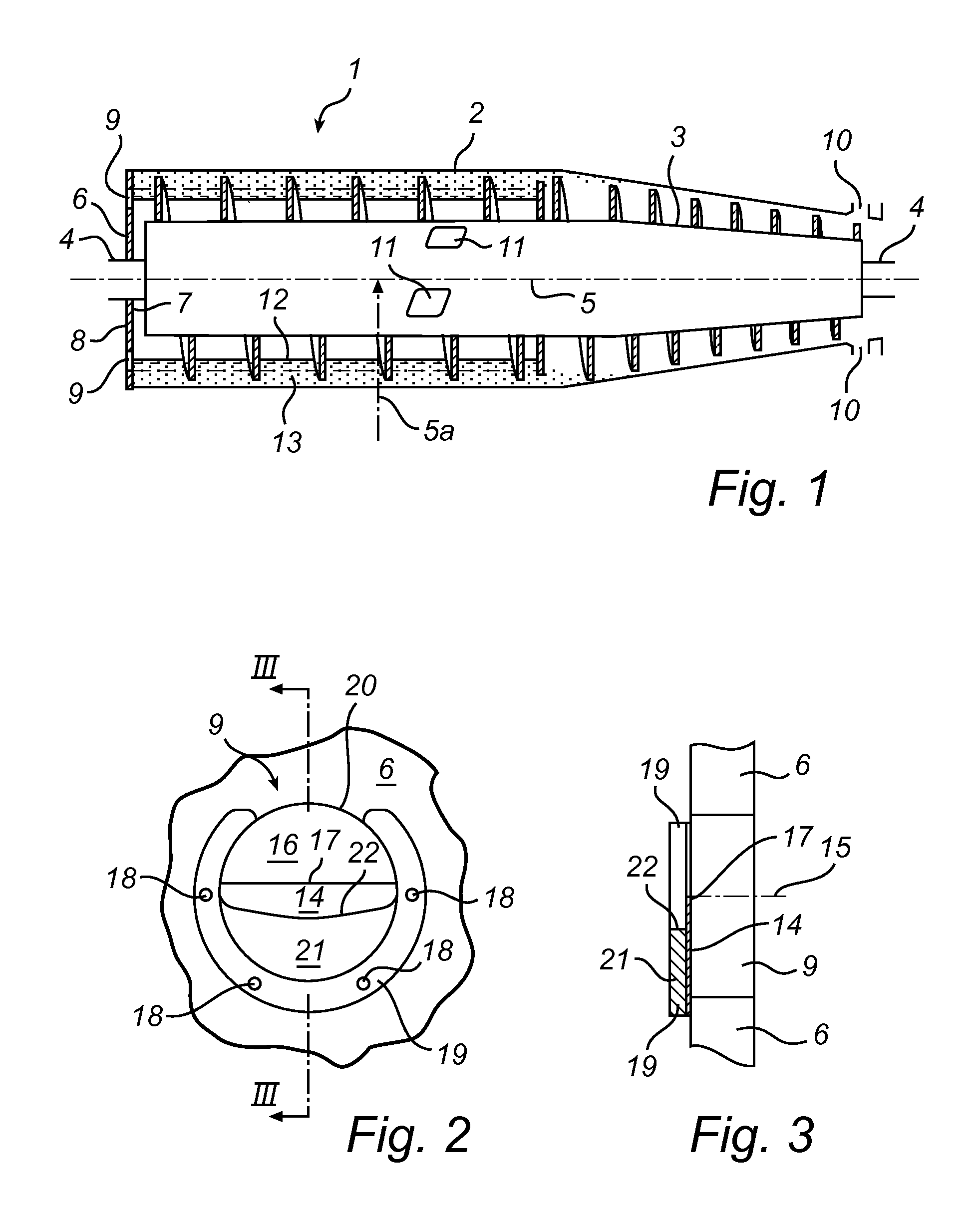
[0030]A rotating body 1 of a prior art centrifugal separator or decanter centrifuge schematically shown in FIG. 1 includes a bowl 2 and a screw conveyor 3 which are mounted on a shaft 4 for rotation around a horizontal axis 5 of rotation. The axis 5 of rotation extends in a longitudinal direction of the bowl 2. Further, the rotating body 1 has a radial direction 5a extending perpendicular to the longitudinal direction.

[0031]For the sake of simplicity directions “up” and “down” are used herein as referring to a radial direction towards the axis 5 of rotation and away from the axis 5 of rotation, respectively.

[0032]The bowl 2 comprises a base plate 6 provided at one longitudinal end of the bowl 2, which base plate 6 has an internal side 7 and an external side 8. The base plate 6 is provided with a plurality of liquid phase outlet passages 9 having external openings in the external side 8 of the base plate. Furthermore the bowl 2 is at an end opposite to the base plate 6 provided with ...


PUM


Abstract

A centrifugal separator includes a rotating body rotating in use around an axis. The rotating body comprises a bowl, which comprises a base at one longitudinal end of said bowl, said base defining a rear longitudinal area. An outlet passage extends through the base and an outlet housing is provided in the rear longitudinal area. The outlet housing is communicating with the outlet passage to receive liquid therefrom and the outlet housing has an outlet opening discharging in use liquid from the rotating body. The outlet opening comprises a weir edge defining in normal use a level of a surface of a liquid in the bowl. The outlet housing is rotatable around an adjustment axis and the outlet opening is placed in a side wall offset from the adjustment axis.

Description

FIELD OF THE INVENTION[0001]The present invention relates to a centrifugal separator, in particular to a decanter centrifuge, including a body configured to rotate during use in a direction of rotation around a horizontal axis of rotation. The axis of rotation extends in a longitudinal direction of the rotating body. The rotating body includes a bowl. The bowl defines a base provided at one longitudinal end of the bowl. The base faces a first rear longitudinal area of the centrifugal separator rear of the base. A first outlet passage extends through the base. A first outlet housing is provided in the first rear longitudinal area. The first outlet housing communicates with the first outlet passage to receive liquid from the first outlet passage. The first outlet housing has a first outlet opening configured to discharge liquid from the rotating body during operation. The first outlet opening includes a first weir edge defined in normal use, a level of a surface of a liquid in the bow...

Claims


Application Information

Patent Timeline
IPC IPC(8): B04B11/00
CPCB04B1/20B04B7/02B04B11/00B04B2001/2083B04B2001/2075B04B11/02B04B13/00
Inventor MADSEN, BENTREIFF, HENRIK
Owner ALFA LAVAL CORP AB
Why Eureka
Try Eureka