
Safety needle

a safety needle and needle technology, applied in the field of medical conditions, can solve the problems of affecting the health of patients, affecting the function of the patient, and the catheter is likely to kink and close, so as to relieve the tension of the pneumothorax and increase the fluid flow

Active Publication Date: 2013-11-21
THE SEABERG
View PDF8 Cites 41 Cited by
  • Summary
  • Abstract
  • Description
  • Claims
  • Application Information

AI Technical Summary

Benefits of technology

This patent describes a safety needle device that prevents injury to organs during needle decompression and also helps in confirming correct needle placement. The device has a hollow needle or cannula and a hollow tube inside it connected with a "pen click" mechanism allowing the sharp point of the device to be exposed or obscured through user action. The device also has a plunger mechanism for dislodging a tissue plug from the needle. The technical effect of this patent is that it provides a safer and more effective tool for needle decompression procedures with improved visual confirmation of correct needle placement.

Problems solved by technology

The needle prescribed by the military services is sharp, creating the possibility of damaging underlying organs after initial penetration through the chest wall.
This small inner diameter of 0.042″ does not provide an effective means for venting pressurized air quickly from the pleural space.
Removal of the needle, leaving the catheter in place, allows better flow, but is not desired, since if it were left in place for long periods it would in essence be an open pneumothorax, and because the catheter is likely to kink and close itself off.
A Veress needle of this conventional configuration may be prone to at least the following shortcomings:(1) Such a needle may not adequately protect a patient if, when the needle is introduced subcutaneously in the vicinity of vital organs (which is often the case), there is a force of sufficient magnitude to overcome the spring bias of the inner tube and thus expose the outer cannula's sharp tip.(2) Such a needle may be prone to clogging, as the generally weak spring bias may be insufficient to overcome the resistive forces of tissue or blood which then may become wedged within the hollow outer cannula.(3) The sharp tip of the Veress needle after use is another potential danger on the battlefield and is a challenge for the military.

Method used


Image

  • Safety needle
  • Safety needle
  • Safety needle

Examples


Embodiment Construction

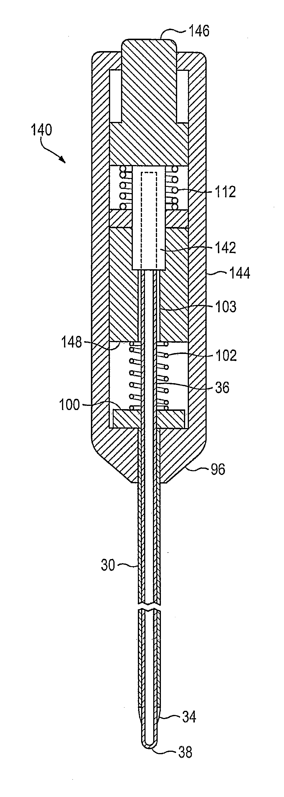
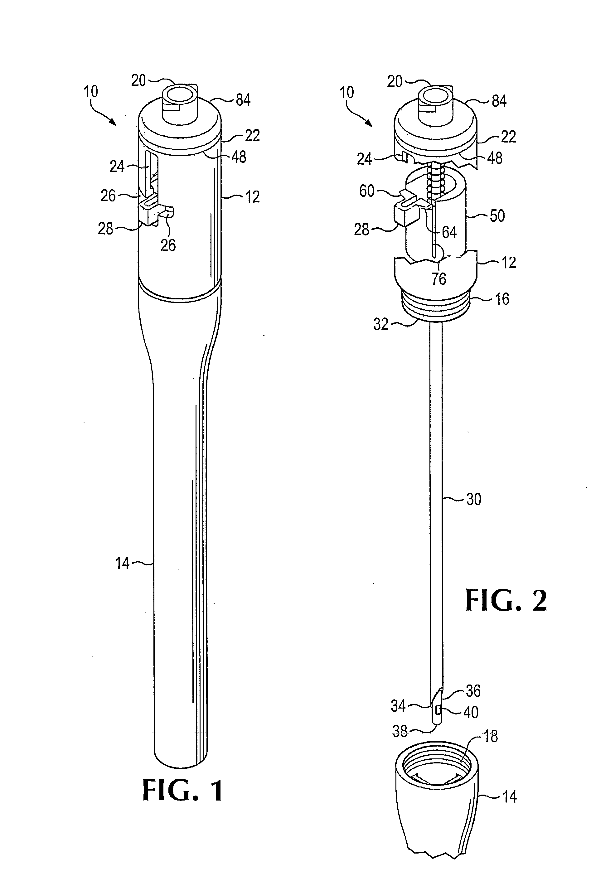
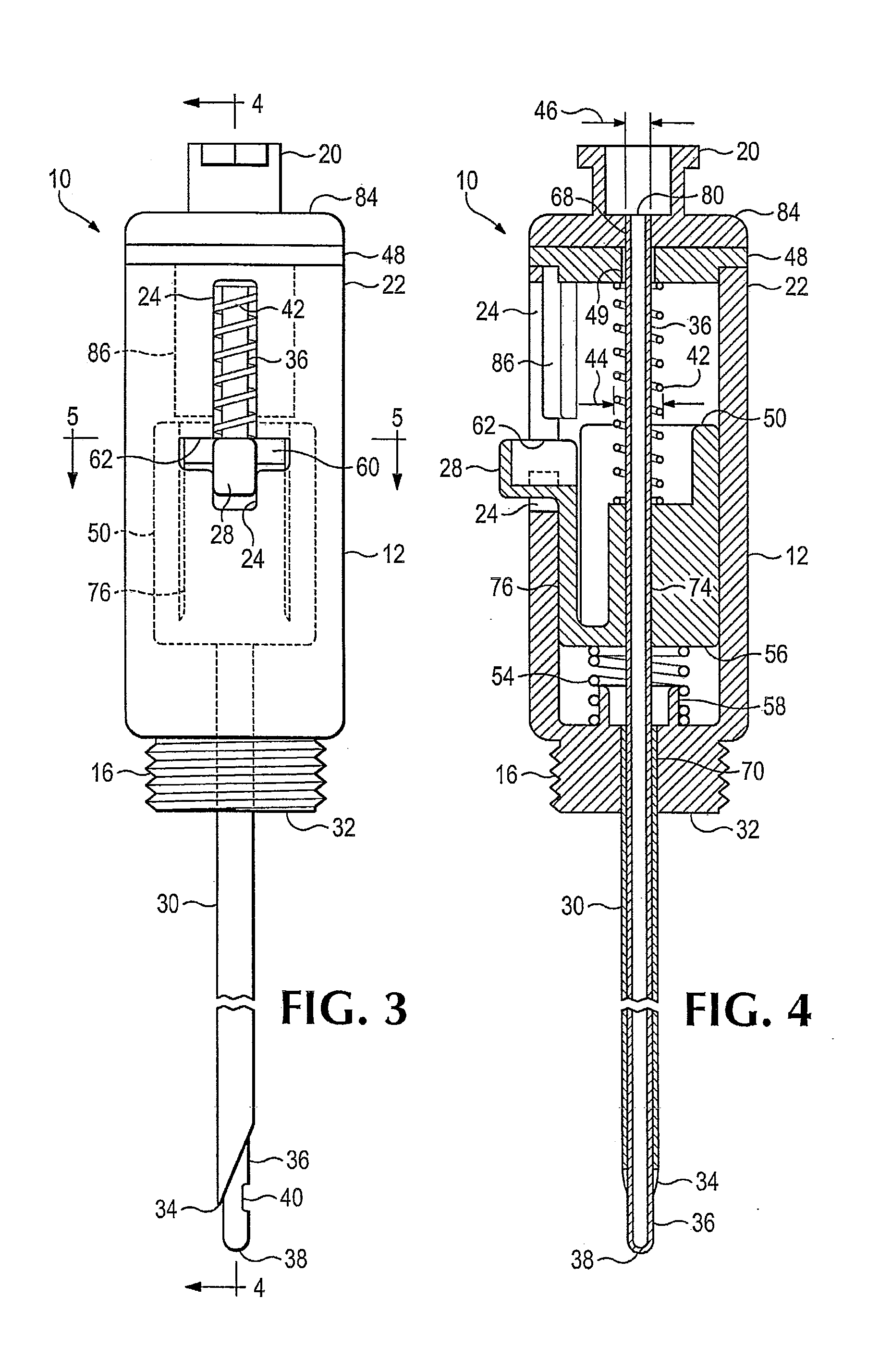
[0031]Referring to the drawings which form a part of the disclosure herein, and referring first to FIGS. 1 and 2, a medical device 10 includes a housing or body 12 to which a generally cylindrical protective outer cover 14 is shown connected in FIG. 1. The cover 14 may be detachably connected to the body 12 as by an externally threaded portion 16 of the body 12 and mating internal threads 18 in the cover 14. Both the body 12 and the cover 14 may be of suitable molded plastic. The device 10 may be packaged in a hard protective case for sterilization and protection in an austere prehospital environment.

[0032]A connector, such as a female Luer fitting 20, may be provided at the proximal end 22 of the body 12, the top end as shown in FIGS. 1 and 2. The body 12 may be generally cylindrical, and defines a slot 24 extending longitudinally along one side near the proximal end 22. The slot 24 pierces the cylindrical wall of the body 12, extending into the interior of the body 12, as will be ...


PUM


Abstract

A medical device including a portion similar to a Veress needle, useful for relief of tension pneumothorax. The device includes a hollow tubular stylet disposed movably within a hollow needle or cutting cannula, and an optionally releasable locking mechanism for keeping the stylet in place protruding distally beyond the sharpened distal end of the cutting cannula to prevent puncture of internal organs after the chest wall has been intentionally punctured. The stylet can also be moved outward from within the cannula to push a plug of tissue from the bore of the cannula. A valve or a connector for a tube may be provided at a proximal end of the stylet.

Description

BACKGROUND OF THE INVENTION[0001]The present invention relates to treatment of medical conditions such as tension pneumothorax and particularly to a device for its treatment.[0002]The U.S. military services currently prescribe needle decompression for treatment of tension pneumothorax, a condition which can be fatal if not quickly relieved. The means of treatment for prehospital care should be compact and as simple as practical.[0003]The needle prescribed by the military services is sharp, creating the possibility of damaging underlying organs after initial penetration through the chest wall. It has been reported as well that the needle occasionally plugs with a tissue “core” as it travels through the chest wall. If the plug is detected, the needle could be flushed using a syringe; however it is not certain that the plug would be detected. A 3.15 inch long, 14 gauge angiocatheter needle is used as the standard of care for the U.S. military. Although the catheter is 14 gauge (0.083″ ...

Claims


Application Information

Patent Timeline
IPC IPC(8): A61M1/00
CPCA61M1/008A61M1/04A61B17/3474A61B17/3496A61M25/0643A61M2005/3212A61M5/321A61M1/84
Inventor HOPMAN, LANCE D.JOHNSON, LANE M.
Owner THE SEABERG
Learn More