Extracorporeal Unit for Inspecting the Insulation of an Electrical Wire of an Implanted Medical Device

a medical device and electrical wire technology, applied in the field of medical devices, can solve the problem of more susceptible to damage of the segment, and achieve the effect of improving the electrical coupling

Active Publication Date: 2013-11-21
THE GUY P CURTIS & FRANCES L CURTIS TRUST
View PDF6 Cites 29 Cited by
  • Summary
  • Abstract
  • Description
  • Claims
  • Application Information

AI Technical Summary

Benefits of technology

[0013]In another embodiment of the present invention, a portion of the lead is tested while the portion remains implanted in a subcutaneous pocket of a patient. For this embodiment, the electrically conductive solution is disposed within the subcutaneous pocket of the patient. Also for this embodiment, the anode and cathode of the voltage source are spaced-apart and attached to a non-conductive tip of a retractor. With the proximal end of the electrical lead electrically connected to the monitor, the retractor tip is immersed in the electrically conductive solution to generate a current, e.g. pulsed current, in the solution. To improve electrical coupling, the tip of the retractor can be L-shaped to align the anode and cathode in a direction substantially parallel to a plane containing a portion of the lead undergoing testing. As the current is generated in the solution, an interrupt signal will be received by the monitor indicating that the electrical lead is defective if there is a break in the lead insulation. For a pacemaker dependent patient, the monitor is replaced by a monitor / pulse generator as described above. For this case, an interrupt signal will be received by the monitor whenever the current in the saline solution interferes with the test / pacing signal. Specifically, the monitor will receive an interrupt signal indicating that the electrical lead is defective whenever there is a break in the lead insulation.

Problems solved by technology

As a practical matter, due to the activity that is typically experienced in the proximal segment of the electrical lead, this segment is more susceptible to damage.

Method used


Image

  • Extracorporeal Unit for Inspecting the Insulation of an Electrical Wire of an Implanted Medical Device
  • Extracorporeal Unit for Inspecting the Insulation of an Electrical Wire of an Implanted Medical Device
  • Extracorporeal Unit for Inspecting the Insulation of an Electrical Wire of an Implanted Medical Device

Examples


Embodiment Construction

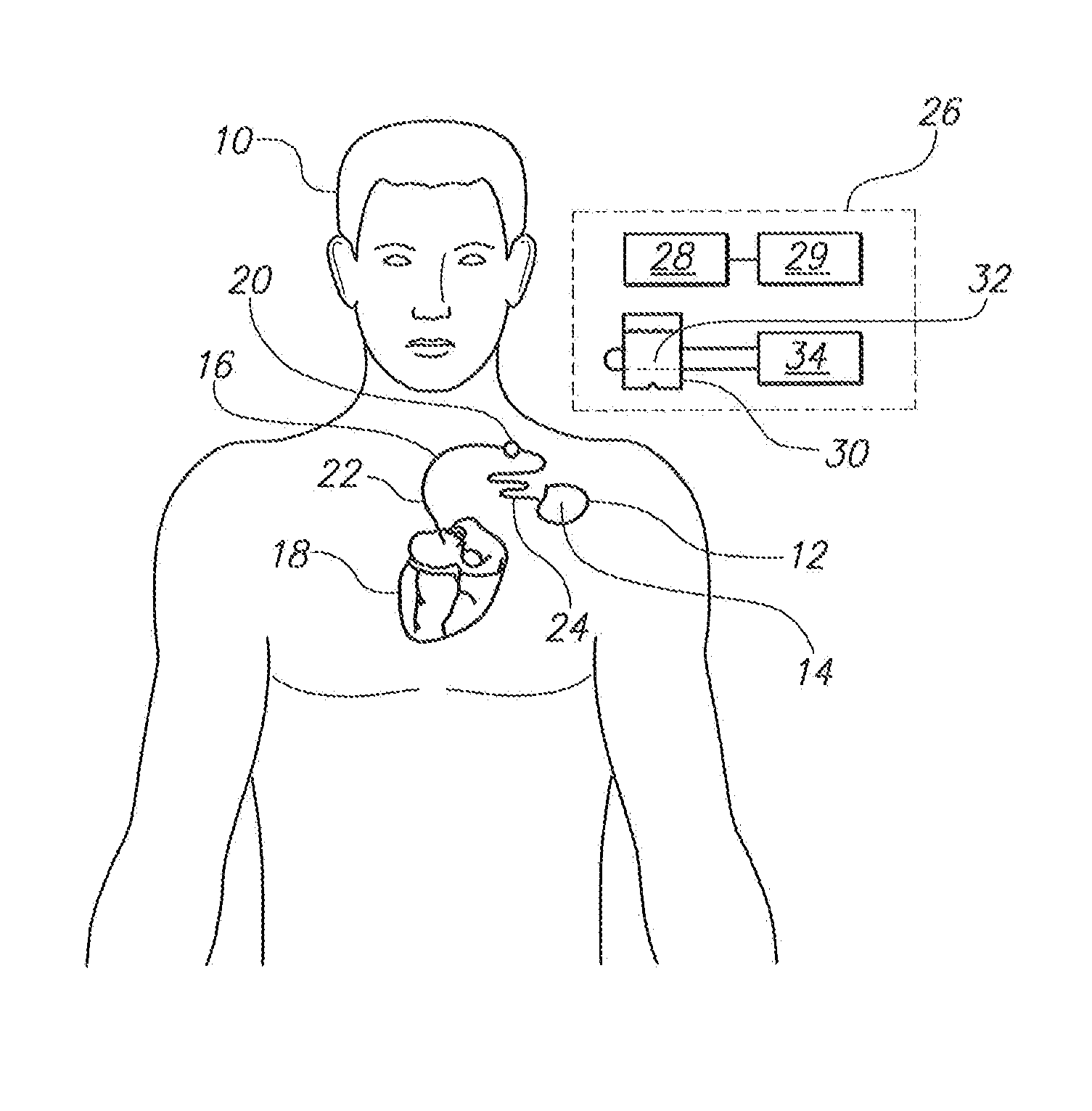
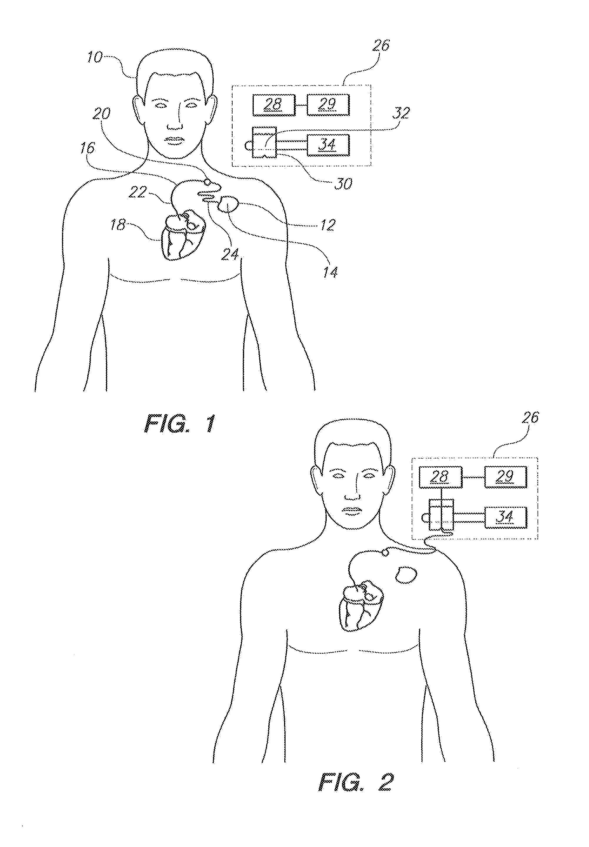
[0021]Referring initially to FIG. 1, a patient 10 is shown with a medical device 12 implanted in his body. As shown, the medical device 12 includes an electronic device 14 and an elongated lead 16. For normal operation of the medical device 12, the proximal end of the lead 16 is electrically connected to the electronic device 14 and the distal end of the lead 16 is attached to the patient's heart 18. For example, the medical device 12 can be a conventional device such as an artificial cardiac pacemaker, an implantable cardioverter defibrillator (ICD), a combination pacemaker / defibrillator or any other implantable medical device known in the pertinent art which has an implanted lead that sends electrical impulses to or receives electrical signals from a patient's organ such as the heart 18.

[0022]For the above-described purposes, the electronic device 14 typically includes an internal battery, pulse generating circuit, a sensor for monitoring the electrical activity of the heart and a...


PUM


Abstract

A system is provided for testing the electrical integrity of an implanted pacemaker or defibrillator lead. The system includes a container holding an electrically conductive solution, such as a saline solution. A voltage source and two electrodes are provided to pass an electrical current through the solution. To use the system, the proximal end of the electrical lead is disconnected from the implanted electronic device, passed through the saline solution and then electrically connected to a device/monitor. During testing, the device/monitor sends a test pulse through the lead and monitors electrical activity in the lead. To test sequential locations along the length of the proximal segment, the segment is drawn through the saline solution and between the electrodes while test pulses are sent and monitored. The monitor detects abnormal electrical activity in the lead indicative of a break in lead insulation.

Description

FIELD OF THE INVENTION[0001]The present invention pertains generally to medical devices. More particularly, the present invention pertains to test equipment for inspecting insulation in bipolar pacemaker leads. The present invention is particularly, but not exclusively, useful as a device for inspecting a proximal segment of a pacemaker lead while a distal segment of the lead remains operationally positioned in a patient's body.BACKGROUND OF THE INVENTION[0002]The implantation of a medical device, such as a pacemaker and / or defibrillator, for the purposes of stimulating and / or controlling the heart muscle activity of a patient, involves positioning one or more electrical leads inside the body of the patient. Specifically, these electrical leads extend through the body between a subcutaneously positioned electronic device and the heart.[0003]Although each electrical lead is essentially unitary along its length, different segments of a lead are subjected to different functional enviro...

Claims


Application Information

Patent Timeline
Patent Type & Authority Applications(United States)
IPC IPC(8): A61N1/37A61N1/39A61B5/276
CPCA61N1/371A61N1/3943A61N1/37A61B2560/0276G01R31/1227A61B5/276A61B5/29
Inventor CURTIS, GUY P.
Owner THE GUY P CURTIS & FRANCES L CURTIS TRUST
Why Eureka
Try Eureka