
Method for determining a measurable target variable and corresponding system

a target variable and measurable technology, applied in the field of sensorfusion technology, can solve the problems of large bias error, small bias error, and large bias error in the speed measurement in this way, and achieve the effect of improving the accuracy of vertical and/or horizontal speed

Active Publication Date: 2013-11-21
SUUNTO OY
View PDF4 Cites 17 Cited by
  • Summary
  • Abstract
  • Description
  • Claims
  • Application Information

AI Technical Summary

Benefits of technology

The invention provides a new method and system for accurately measuring target variables in a mobile device, such as speed, altitude, and pressure. The method uses sensors in a wristop device or a portable device without a display, and can detect rapid changes in the target variable and alter the filtering level accordingly. The strength of the filtering is increased when the accuracy of the measurement weakens, and the method reacts faster to variations in conditions to provide more real-time information to the user. Overall, the invention improves accuracy and reliability of speed, altitude, and pressure measurements in various movement and ambient conditions.

Problems solved by technology

GPS speed on the wrist or elsewhere on the body contains a great deal of noise, but has a very small bias error, i.e. a systematic error.
However, there can be even a large bias error in speed measured in this way.
Accordingly, the best accuracy of speed estimated from acceleration is poorer than when using GPS.
Similar problems also relate to the GPS-based determining of altitude and vertical speed.
Further, a somewhat similar problem also relates to the determining of altitude information with the aid of a pressure sensor, though in this case the errors are caused by slow (low-frequency) variations in atmospheric pressure.

Method used


Image

  • Method for determining a measurable target variable and corresponding system
  • Method for determining a measurable target variable and corresponding system
  • Method for determining a measurable target variable and corresponding system

Examples


Embodiment Construction

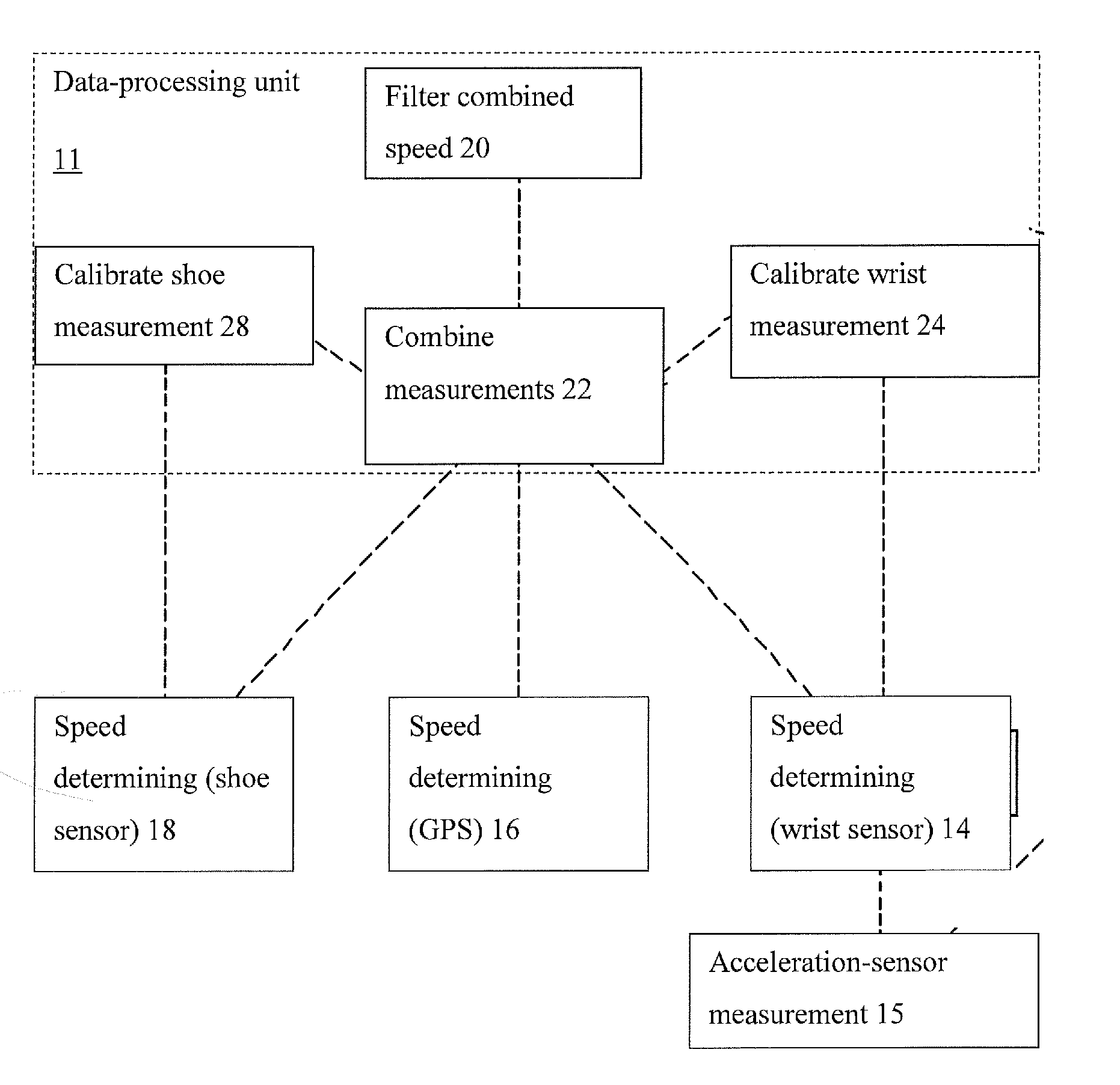
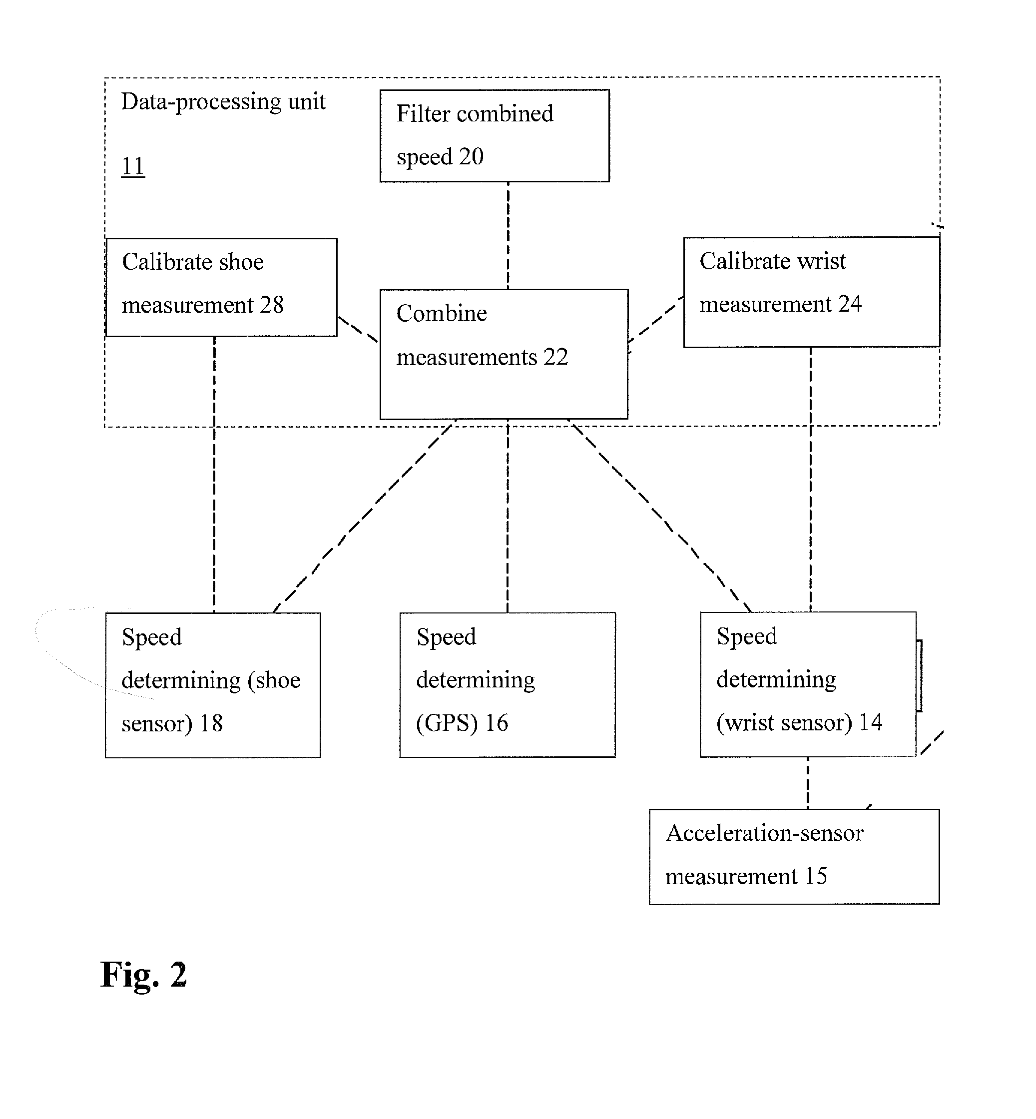
[0044]The basic principle of the invention is first examined with the aid of the object model shown in FIG. 2. Three different ways or methods of determining speed are shown by way of example, speed determining 14 (a first speed determination 14) made on a wrist using acceleration-sensor measurement 15 (e.g., a wristop computer), GPS-based speed determining 16 (a second speed determination 16), and speed determining 18 (a third speed determination 18) made using a shoe sensor (typically based on the acceleration of the foot). The velocities determined are combined centrally with the aid of data processing 22 (a processor 22) in a data processing unit 11. In the example of FIG. 2, information on the person's state of motion obtained from the acceleration measurement 15 is exploited in a filtering 20 of the combined speed.

[0045]FIG. 2 also illustrates how the system can be used for the auto-calibration of the measurements, with the aid of first and second calibration stages 24 and 28,...


PUM


Abstract

The invention relates to a method and a system for determining a target variable to be measured in a mobile device. A first physical variable is measured with the aid of a first sensor and a second physical variable with the aid of a second sensor. The second physical variable is different to the first physical variable, or is measured using a different technique. The value of the target variable is calculated with the aid of the measurement of the first and second physical variables. An estimate for the target variable is determined with the aid of at least the measurement of the first physical variable. At least a first error estimate is determined, which depicts the accuracy of the measurement of the first physical variable. The estimate of the target variable is filtered using both the first error estimate and the measurement of the second physical variable.

Description

RELATED APPLICATIONS[0001]The present application claims priority to U.S. Provisional Patent Application Ser. No. 61 / 649,617 titled METHOD FOR DETERMINING A MEASURABLE TARGET VARIABLE AND CORRESPONDING SYSTEM, and filed on May 21, 2012.FIELD OF THE INVENTION[0002]The invention relates to sensor-fusion technology in mobile devices, i.e. more specifically the processing of information provided by many sensors. The invention particularly relates to improving the accuracy of a target variable measured with the aid of a mobile device or system. The sensors can be, for example, a GPS sensor or pressure sensor, as well as an acceleration sensor. The speed and / or altitude of the target variable can be measured using one or more of the sensors. The mobile device can be, for example, a wristop computer, a mobile telephone, other portable device or a sensor unit, or some functional combination of these.BACKGROUND OF THE INVENTION[0003]GPS speed on the wrist or elsewhere on the body contains a ...

Claims


Application Information

Patent Timeline
IPC IPC(8): G01C25/00G01P21/00G01L27/00
CPCG01C25/00G01L27/00G01P21/00G01C22/006A63B24/0062A46B3/00A43B3/00
Inventor NIEMINEN, HEIKKILINDMAN, ERIK
Owner SUUNTO OY
Learn More