Air conditioning device for vehicle

a vehicle and air conditioning technology, applied in the field of vehicle air conditioning apparatus, can solve the problems of difficulty in acquiring exhaust heat that can heat the air by using electric motors without engines, and the above-mentioned vehicle air conditioning apparatus is not applicable to electric cars, so as to prevent the mileage of the vehicle from dropping, maintain the dehumidification capability, and reduce power consumption

Active Publication Date: 2013-11-28
SANDEN CORP
View PDF10 Cites 25 Cited by
  • Summary
  • Abstract
  • Description
  • Claims
  • Application Information

AI Technical Summary

Benefits of technology

[0030]According to the present invention, it is possible to prevent a frost from being formed on the heat exchanger, and therefore to maintain the dehumidifying capability during a heating and dehumidifying operation under a cool environment.
[0031]According to the present invention, a passenger of the vehicle can select the switching mode among the first switching mode, the second switching mode and the third switching mode. Therefore, by selecting the second switching mode or the third switching mode which has lower power consumption than the first switching mode, it is possible to prevent the mileage of the vehicle from dropping while continuing to perform air conditioning operation in the vehicle interior.
[0032]According to the present invention, it is possible to acquire an optimum quantity of the heat absorbed into the refrigerant in the outdoor heat exchanger, and therefore to maintain the temperature and the humidity of the vehicle interior in good conditions.

Problems solved by technology

Generally, an electric car uses an electric motor as a power source, and it is difficult to acquire the exhaust heat that can heat the air by using the electric motor without an engine.
Therefore, the above-mentioned vehicle air conditioning apparatus is not applicable to electric cars.

Method used


Image

  • Air conditioning device for vehicle
  • Air conditioning device for vehicle
  • Air conditioning device for vehicle

Examples


embodiment 1

[0068]FIG. 1 to FIG. 8 show Embodiment 1 of the present invention.

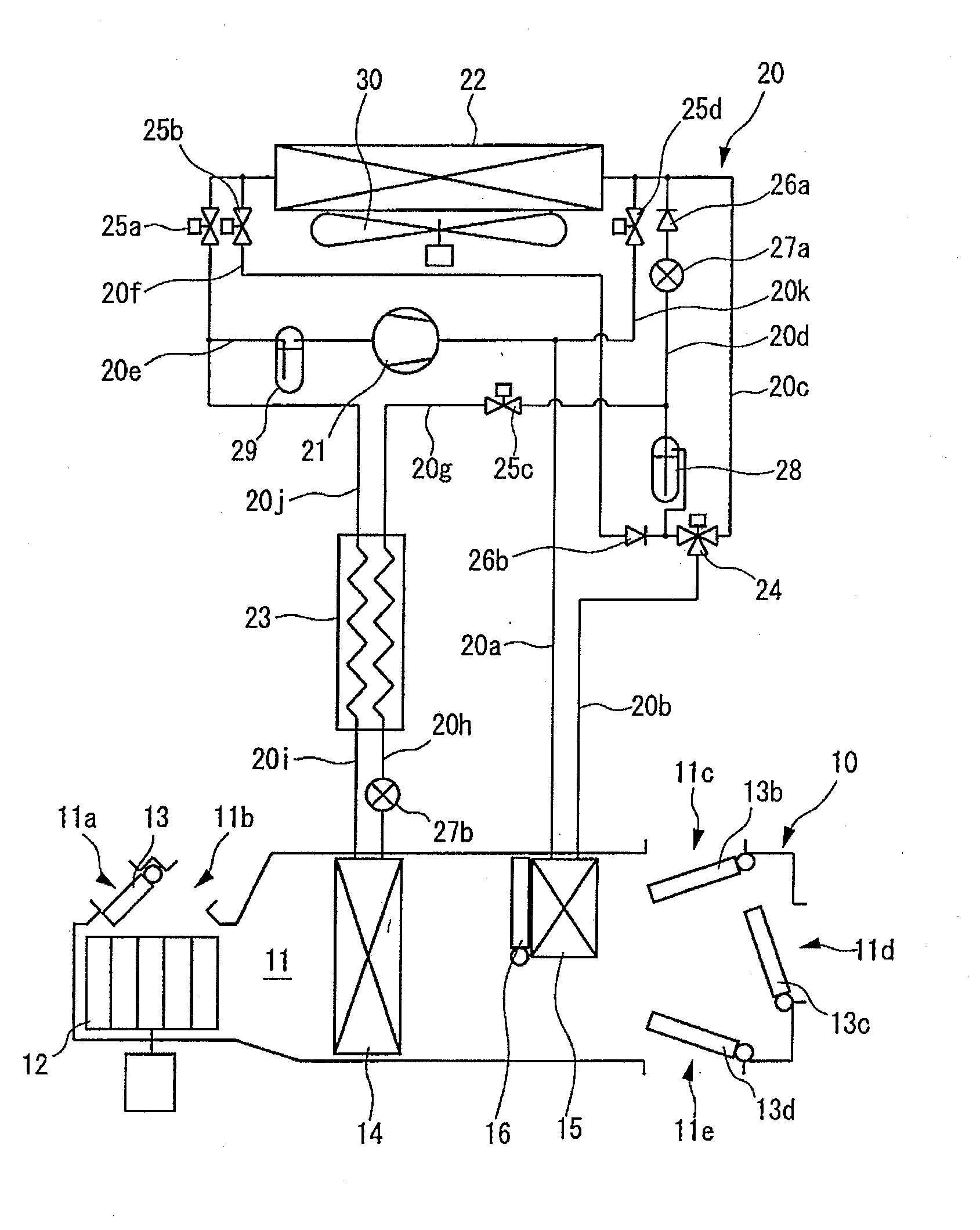
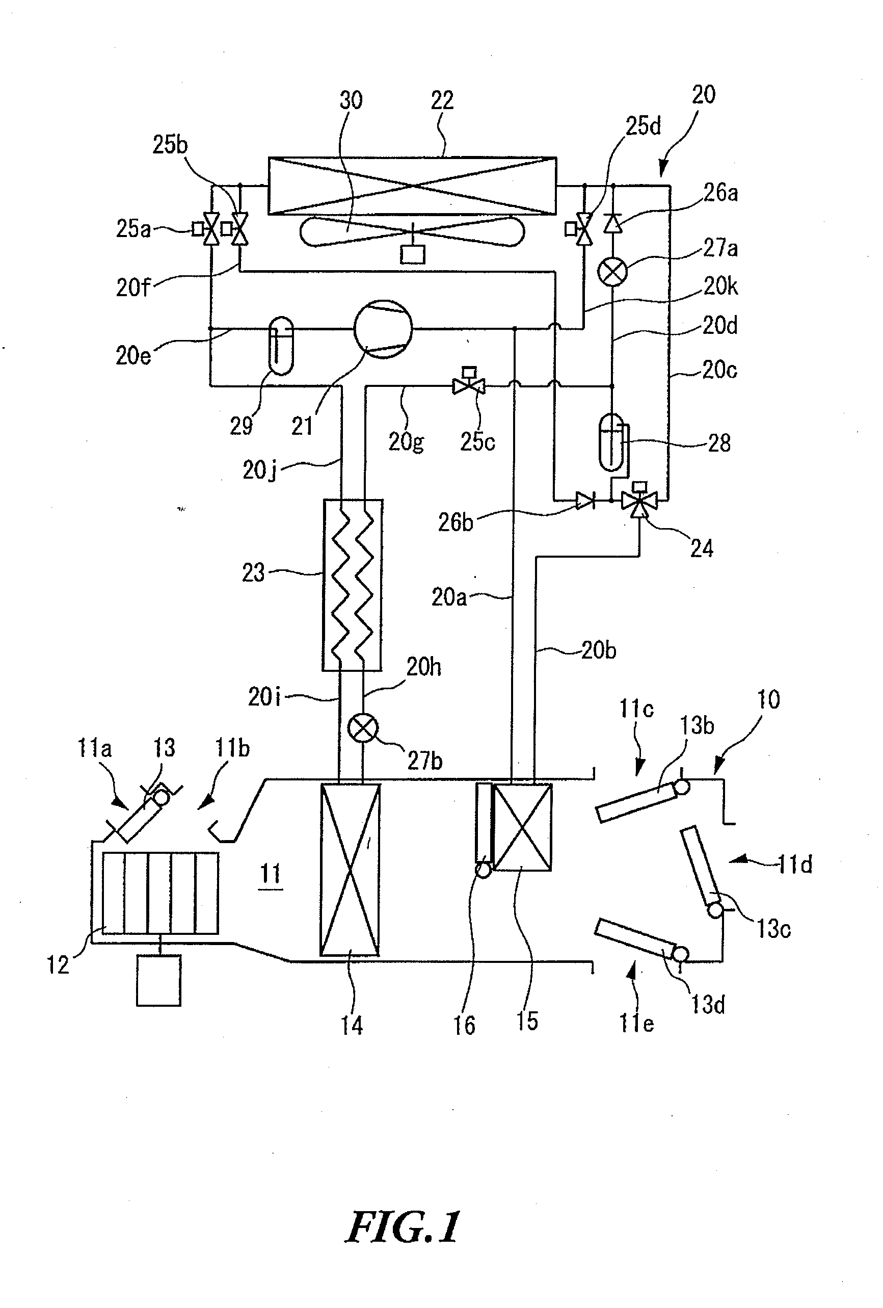
[0069]As shown in FIG. 1, the vehicle air conditioning apparatus according to the present invention includes an air conditioning unit 10 provided in the vehicle interior, and a refrigerant circuit 20 formed across the vehicle interior and the outdoor.

[0070]The air conditioning unit 10 includes an air flow passage 11 that allows the air to be supplied to the vehicle interior to pass through. An outdoor air inlet 11a and an indoor air inlet 11b are provided in the first end side of the air flow passage 11. The outdoor air inlet 11a is configured to allow the outdoor air to flow into the air flow passage 11, and the indoor air inlet 11b is configured to allow the indoor air to flow into the air flow passage 11. Meanwhile, a foot outlet 11c, a vent outlet 11d and a defroster outlet 11e are provided in the second end side of the air flow passage 11. The foot outlet 11c is configured to allow the air flowing through the air...

embodiment 3

[0122]FIGS. 13 to 15 show Embodiment 3 of the present invention. Here, the same components are assigned the same reference numerals as in the above-described embodiments.

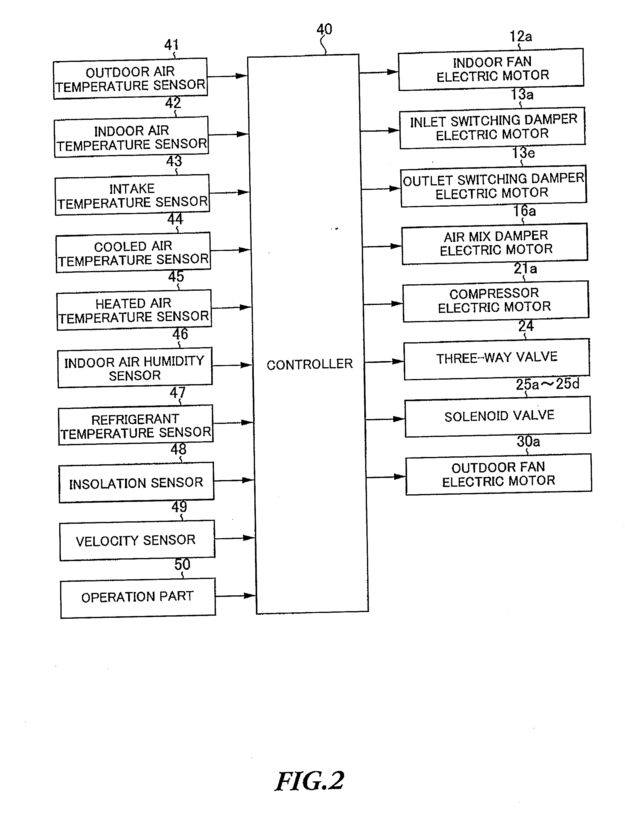
[0123]In the vehicle air conditioning apparatus according to the present embodiment, an electronic expansion valve 27c with the adjustable opening is employed instead of the first expansion valve in the refrigerant circuit 20 of Embodiment 1. In addition, the outdoor heat exchanger 22 is provided with a pressure sensor 51 to detect pressure P of the refrigerant in the outdoor heat exchanger 22. As shown in FIG. 14, the electronic expansion valve 27c and the pressure sensor 51 are connected to the output side and the input side of the controller 40, respectively.

[0124]In the vehicle air conditioning apparatus having the above-described configuration, during the heating and dehumidifying operation, the controller 40 performs a process to control the temperature of the heat exchanger to prevent a frost from being forme...

embodiment 4

[0134]FIGS. 16 and 17 show Embodiment 4 of the present invention. Here, the same components are assigned the same reference numerals as in the above-described embodiments.

[0135]The vehicle air conditioning apparatus according to the present invention has the same configuration as in Embodiment 3, and the electronic expansion valve 27c is opened and closed as a process to control the temperature of the heat exchanger. Now, the operation of the controller 40 in this process will be explained with reference to the flowchart shown in FIG. 16.

[0136](Step S31)

[0137]In step S31, the CPU determines whether or not the outdoor air temperature Tam is the predetermined temperature T1 (e.g. 10 degrees centigrade) or lower. When determining that the temperature Tam is the predetermined temperature T1 or lower, the CPU moves the step to step S34. On the other hand, when determining that the temperature Tam is higher than the predetermined temperature T1, the CPU moves the step to step S32.

[0138](S...


PUM


Abstract

A vehicle air conditioning apparatus is provided to prevent a frost from being formed on a heat exchanger under the condition that the outdoor temperature is low. During a heating and dehumidifying operation, the third solenoid valve 25c is closed when outdoor temperature Tam is predetermined temperature T1 or lower, or when temperature Thex of the refrigerant flowing out of the outdoor heat exchanger 22 is a predetermined temperature T2 or lower and temperature Te detected by the cooled air temperature sensor 44 is temperature Tet-β or lower. By this means, during the heating and dehumidifying operation, when a frost is likely to be formed on the heat exchanger 14, it is possible to prevent the refrigerant from flowing into the heat exchanger 14, and to prevent a frost from being formed on the heat exchanger 14.

Description

CROSS-REFERENCES TO RELATED APPLICATIONS[0001]This application claims the benefit of Japanese Patent Application No. 2011-027304, filed Feb. 10, 2011, Japanese Patent Application No. 2011-040132, filed Feb. 25, 2011, and Japanese Patent Application No. 2011-098248, filed Apr. 26, 2011, which are incorporated herein by reference.TECHNICAL FIELD[0002]The present invention relates to a vehicle air conditioning apparatus applicable to, for example, electric cars.BACKGROUND ART[0003]Conventionally, as a sort of apparatus, there has been known a vehicle air conditioning apparatus that includes: a compressor configured to compress and discharge a refrigerant; a radiator provided in the vehicle interior and configured to release the heat from the refrigerant; a heat exchanger provided in the vehicle interior and configured to absorb the heat into the refrigerant and an outdoor heat exchanger provided outside the vehicle interior and configured to release the heat from or absorb the heat int...

Claims


Application Information

Patent Timeline
Patent Type & Authority Applications(United States)
IPC IPC(8): B60H1/00
CPCB60H1/00485B60H1/00642B60H1/00B60H1/00007B60H1/00385B60H1/3204F25B1/00F25B29/003F25B47/02F25B49/02B60H2001/3279B60H2001/3263F25B41/24F25B41/20B60H1/00921B60H2001/00957F25B47/006F25B2700/2117
Inventor SUZUKI, KENICHIMIYAKOSHI, RYOTAKEI, HIDENORIYAMASHITA, KOUHEI
Owner SANDEN CORP
Why Eureka
Try Eureka