
A temperature and humidity control air conditioning system

An air-conditioning system, temperature and humidity technology, applied in the field of HVAC, can solve the problems that the output is difficult to meet the peak load demand, the load capacity of the radiation unit is low, and the response speed of the instantaneous load is slow, so as to reduce the installed capacity, ensure the dehumidification capacity, and improve the comfort degree of effect

Active Publication Date: 2022-03-08
JIANGSU HUIJU ARCHITECTURE TECH CO LTD
View PDF5 Cites 0 Cited by
  • Summary
  • Abstract
  • Description
  • Claims
  • Application Information

AI Technical Summary

Problems solved by technology

[0004] However, the load bearing capacity of the radiation unit is low. Under heavy load conditions (such as hot and humid areas), the output is difficult to meet the peak load demand, and the response speed to the instantaneous load is slow; and the centralized cold source produces 7°C chilled water, which is affected by Influenced by comprehensive factors such as pipeline temperature rise, hydraulic imbalance, and extreme hot and humid outdoor conditions, the dehumidification capacity is insufficient, and there is a risk of condensation at the end, which seriously affects the operating efficiency of the entire system
In addition, the fresh air adopts a centralized fresh air unit, which lacks household regulation, resulting in a large waste of energy and lack of system flexibility

Method used


Image

  • A temperature and humidity control air conditioning system
  • A temperature and humidity control air conditioning system
  • A temperature and humidity control air conditioning system

Examples


Embodiment Construction

[0071] In order to more clearly illustrate the technical solutions in the embodiments of the present invention or the prior art, the following will briefly introduce the drawings that need to be used in the description of the embodiments or the prior art. Obviously, the accompanying drawings in the following description are only These are some embodiments of the present invention. Those skilled in the art can also obtain other drawings based on these drawings without creative work.

[0072] In order to make the drawing concise, each drawing only schematically shows the parts related to the present invention, and they do not represent the actual structure of the product. In addition, to make the drawings concise and easy to understand, in some drawings, only one of the components having the same structure or function is schematically shown, or only one of them is marked. Herein, "a" not only means "only one", but also means "more than one".

[0073] It should also be further u...


PUM


Abstract

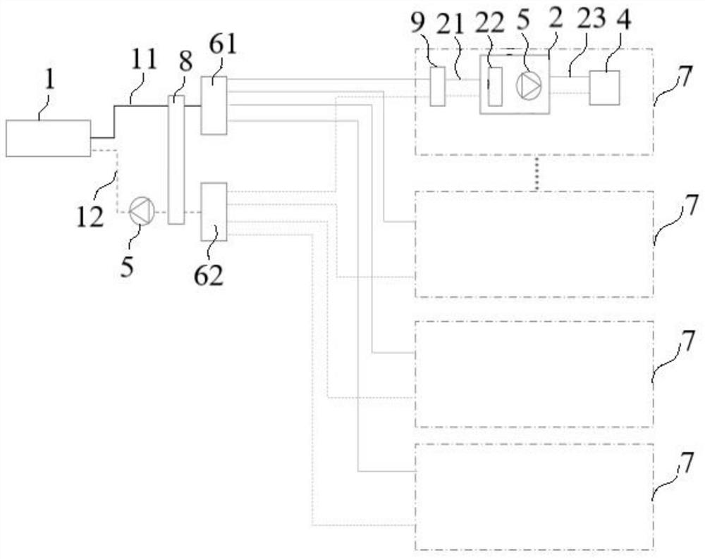
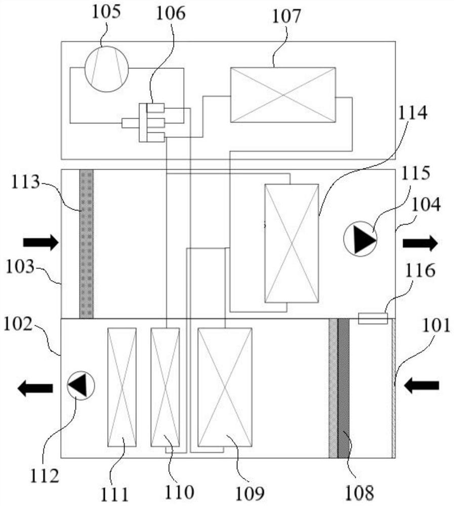
The invention belongs to the field of heating and ventilation, and discloses an air conditioning system with separate temperature and humidity control, which includes an independently operated radiation system and a fresh air dehumidification unit; the radiation system includes a centralized cold and heat source host; the hydraulic module includes a primary side pipeline, a heat exchanger and The secondary side pipeline, the primary side pipeline is connected with the main engine of the centralized cold and heat source, and the primary side pipeline and the secondary side pipeline exchange heat through the heat exchanger; the end is set at the user end and communicated with the secondary side pipeline; The fresh air dehumidification unit is set on the user end to control the moisture content of the fresh air through isothermal dehumidification. The invention uses an independent fresh air dehumidification unit for isothermal dehumidification, which can ensure the dehumidification capacity of the system and improve the operation effect, and can be adjusted independently at the household end to improve flexibility; the radiation system operates independently, reducing the installed capacity of the centralized cold and heat source host , which reduces the construction and maintenance costs of the machine room, and the intercooled water can be used as the cold source in summer working conditions, which increases the evaporation temperature, improves the cooling efficiency, and reduces energy consumption.

Description

technical field [0001] The invention relates to the field of heating and ventilation, in particular to an air conditioning system with separate temperature and humidity control. Background technique [0002] With the improvement of the pursuit of quality of life, users have put forward higher requirements for living comfort, and the "three constants" (constant temperature, constant humidity, constant oxygen) system with temperature and humidity separate control as the technical core has gradually become the standard of high-tech housing configuration. [0003] At present, the residential air-conditioning system with separate temperature and humidity control generally adopts a centralized cold and heat source main engine to generate chilled water supply terminal and centralized fresh air unit in summer. The radiant unit bears the main indoor sensible heat load, and the fresh air unit bears the indoor latent heat load and a small part of sensible heat. load. In winter, the c...

Claims


Application Information

Patent Timeline
Patent Type & Authority Patents(China)
IPC IPC(8): F24F11/88F24F11/89F24F11/64F24F3/14F24F13/28F25B13/00F24D3/10G06Q50/06
CPCF24F11/88F24F11/89F24F11/64F24F3/14F24F13/28F25B13/00F24D3/10G06Q50/06F24F2003/144
Inventor 张国华王亮韩园园
Owner JIANGSU HUIJU ARCHITECTURE TECH CO LTD
Learn More