A thermoelectric dehumidification device

A technology of thermoelectricity and hot end surface, which is applied in heating methods, household heating, household heating, etc., can solve the problems of poor dehumidification effect of air flow and inability of air flow to cool fins smoothly, so as to improve the dehumidification effect and accelerate the development of The effect of falling down

Active Publication Date: 2021-11-30
NORM PACIFIC AUTOMATION
View PDF16 Cites 0 Cited by
  • Summary
  • Abstract
  • Description
  • Claims
  • Application Information

AI Technical Summary

Problems solved by technology

However, during the slow sliding of the water droplets, the air flow still continues to pass through the fins 23. When the air flow passes through the position covered by the water droplets, the air flow cannot contact the fins at this position, causing the air flow to fail to cool down smoothly. Water droplets condense on the fins, resulting in poor dehumidification effect of the air flow entering the dehumidifier

Method used


Image

  • A thermoelectric dehumidification device
  • A thermoelectric dehumidification device
  • A thermoelectric dehumidification device

Examples


Embodiment Construction

[0067] In order to clearly illustrate the present invention, a number of embodiments are given and described in detail with reference to the accompanying drawings as follows.

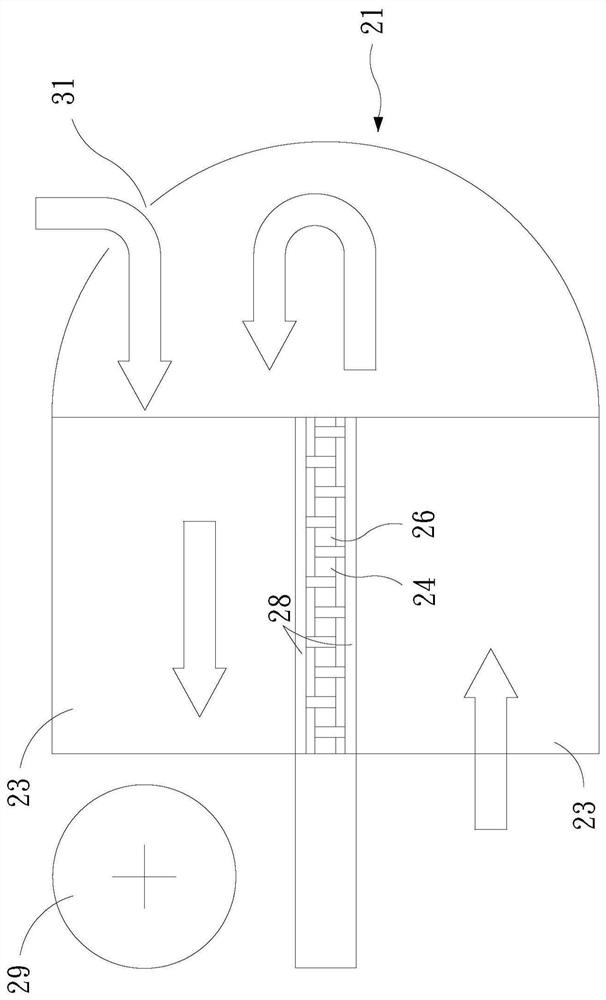
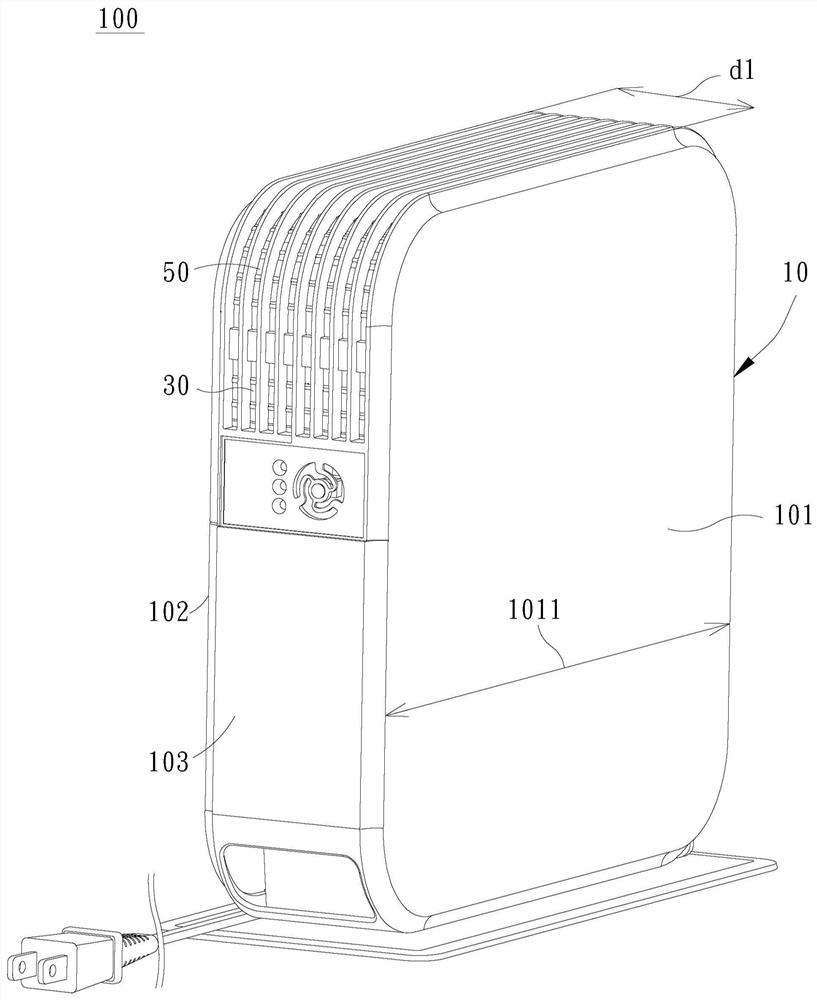
[0068] see Figure 2 to Figure 8 , the thermoelectric dehumidification device 100 of the present invention at least includes a housing 10, a thermoelectric element 20, a first air inlet 30, a second air inlet 40, an air outlet 50, a condensing fin group 60, and a cooling fin group 70 and a fan 80, wherein, the first air inlet 30, the second air inlet 40 and the air outlet 50 are located in the housing 10, and the thermoelectric element 20, the condensing fin group 60, the cooling fin group 70 and the fan 80 are provided in the housing 10.

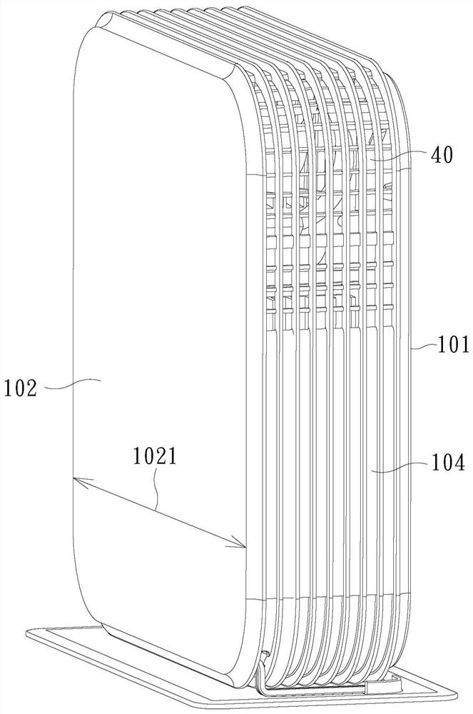
[0069] The casing 10 at least includes a first side 101, a second side 102, a third side 103 and a fourth side 104, wherein the first side 101 and the second side 102 are oppositely arranged with a first distance d1 apart, The horizontal length 1011 of the first si...


PUM


Abstract

The invention discloses a thermoelectric dehumidification device, which comprises: a first air inlet, a second air inlet and an air outlet arranged in a casing, and a thermoelectric element, a condensing fin group, and a heat dissipation device are arranged in the casing. The fin set and a fan, the thermoelectric element has a cold end face and a hot end face, the condensing fin set is connected to the cold end face, and the bottom side of each condensing fin of the condensing fin set is gradually inclined downward, and the cooling fin set It is connected to the hot end surface, and the fan is located between the second air inlet and the heat dissipation fin group; through the inclined design of the bottom side of each condensing fin, the water droplets condensed on the condensing fin after the air flow enters the housing can be It slides down quickly, and after the dehumidified low-temperature airflow is mixed with the external airflow entering from the second air inlet, it is pushed by the fan to pass through the heat dissipation fins, and effectively take away the heat energy on the heat dissipation fins, so as to increase the efficiency of the thermoelectric dehumidification device. Dehumidifying effect.

Description

technical field [0001] The invention relates to a thermoelectric dehumidification device, in particular to a thin thermoelectric dehumidification device which is applied to indoor dehumidification and has higher dehumidification efficiency than the traditional thermoelectric dehumidification device. Background technique [0002] Generally, the traditional dehumidifier uses the compressor to push the refrigerant to circulate in the pipeline including the condenser and the evaporator. Due to the pressure difference, there is a liquid state and a gas state change. At the evaporator, when the refrigerant evaporates from a liquid state to a gas state in the tube, it absorbs heat. , lower the temperature of the air sucked from outside the machine and flow through the pipe, so that the water vapor in the air will condense into water droplets due to the temperature drop, and the air after dehumidification will be cooled at the condenser and sent out after being compressed by the comp...

Claims


Application Information

Patent Timeline
Patent Type & Authority Patents(China)
IPC IPC(8): F24F3/14F24F13/30
CPCF24F3/14F24F13/30F24F2003/1446
Inventor 黄宏灿翁文昱
Owner NORM PACIFIC AUTOMATION
Why Eureka
Try Eureka