Water-powered generator

a generator and water-powered technology, applied in the direction of electric generator control, machine/engine, vessel construction, etc., can solve the problems of non-permanent use of such fuels, non-environmental protection, air pollution and radiation leakage, etc., and achieve the effect of not costing a lot and enhancing the durability of the generation system

Inactive Publication Date: 2013-11-28
BANG BOO HYEON
View PDF8 Cites 27 Cited by
  • Summary
  • Abstract
  • Description
  • Claims
  • Application Information

AI Technical Summary

Benefits of technology

[0012]According to a first embodiment of the present invention, first, the interior of the side column is hollow, and most of the side column is submerged in water, so it is not influenced by sea wind, by which electric power can be generated in stable state.
[0013]Second, a waterwheel can be positioned in the direction of water with the aid of a steering rudder engaged at a lower side of a ship body like a steering rudder of a yacht.
[0014]Third, since a generator is driven by a chain provided at a center portion of a waterwheel and teeth provided at a horizontal rotary shaft, an acceleration device formed of a plurality of gears is not used, so the facility does not

Problems solved by technology

The above listed electric power generation methods require a huge amount of energy source which is required for driving electric power generation facilities and a large capacity of electric power generation facilities along with some limits in the selections of installation places.
In terms of the fossil fuels such as petroleum and coal which are used as an energy source in the thermal power generation, their reserves are very limited, so the continuous use of such fuels may cause some problems such as resource depletions, for which the uses of such fuels are not permanent.
In addition, such fuels may cause air pollutions and radiation leak, so they are considered non-environmentally friendly.
The electric power generation method of converting solar energy or wind force energy into electric energy and storing in batteries is greatly limited by weather and surrounding environments.
In addition, since the tidal force based power generation method can genera

Method used


Image

  • Water-powered generator
  • Water-powered generator
  • Water-powered generator

Examples


first embodiment

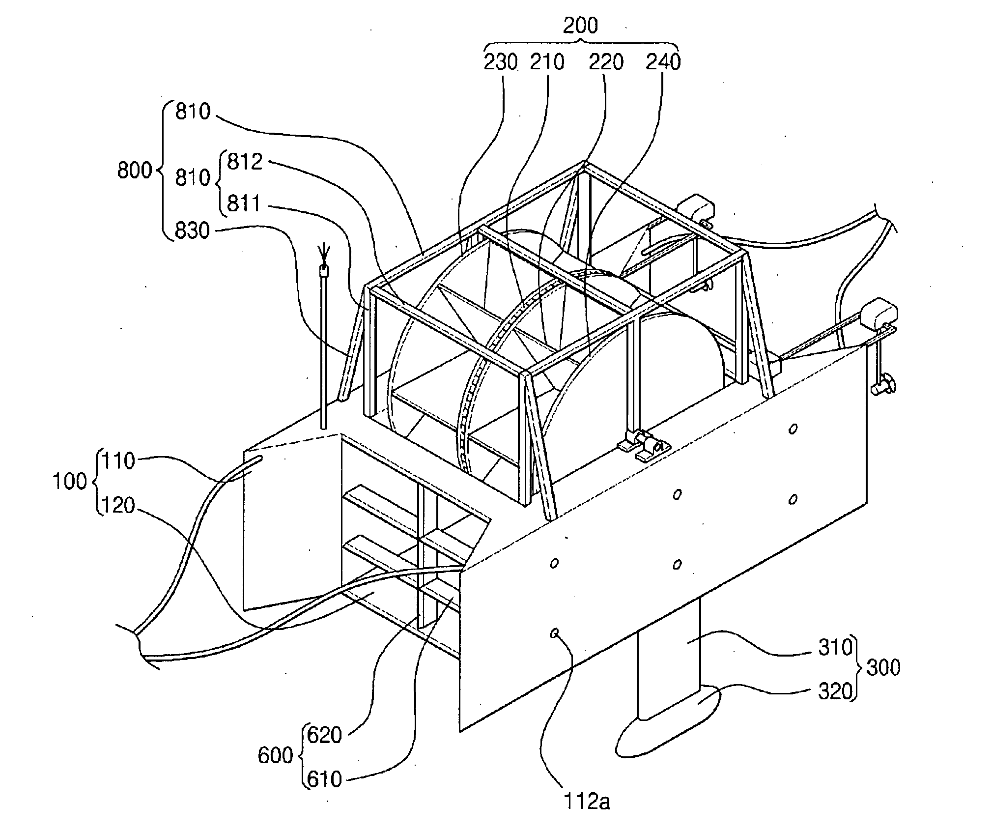
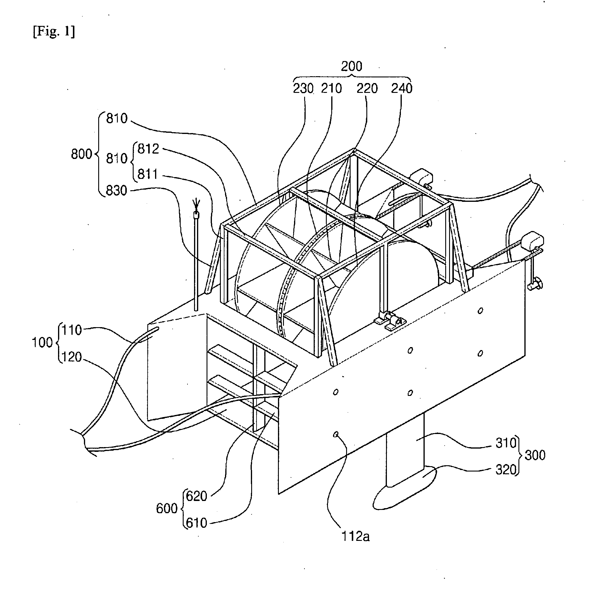
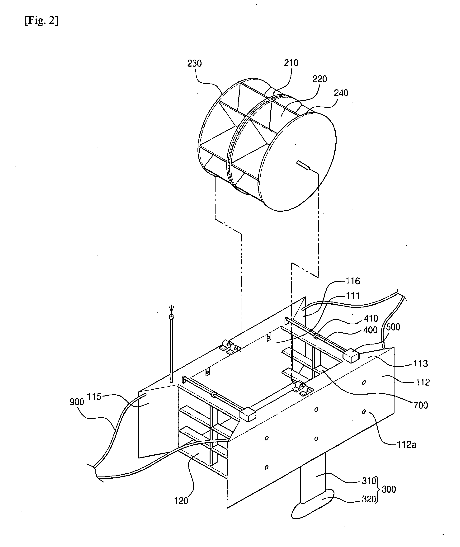
[0034]FIG. 1 is a perspective view illustrating a water-powered generator according to a first embodiment of the present invention. FIG. 2 is a view illustrating a ship body and a frame of a water-powered generator of FIG. 1. FIG. 3 is a view illustrating an anchor and a rope of a water-powered generator of FIG. 1. FIG. 4 is a cross sectional view illustrating a waterwheel of a water-powered generator of FIG. 1.

[0035]The water-powered generator according to a first embodiment of the present invention comprises a ship body 100 which is formed of a side column 110 provided at either side and a bottom plate 120 interconnecting the lower sides of the side column 110 and which floats on water; a waterwheel 200 which is provided in the space made by the side column 110 and the bottom plate 120 and has a chain 210 at an outer surface; a steering rudder 300 which downwardly extends from a lower surface of the side column 110; a horizontal rotary shaft 400 both ends of which are connected to...

second embodiment

[0098]FIG. 5 is a perspective view illustrating a water-powered generator according to a second embodiment of the present invention. FIG. 6 is a side view illustrating a water-powered generator according to a second embodiment of the present invention. FIG. 7 is a front view illustrating a water-powered generator according to a second embodiment of the present invention. FIG. 8 is a plane view illustrating a water-powered generator according to a second embodiment of the present invention.

[0099]As shown in FIGS. 5 to 8 the water-powered generator “A2” according to a second embodiment of the present invention comprises:

[0100]a ship body 1 which includes a side column 13 formed at either side, a bottom plate 15 connecting the lower side of the side column 13, a water inlet port 19 which protrudes from a front side of the side column 13 and has a space 10 formed at a central portion to engage a waterwheel 2, the ship body floating on water;

[0101]a waterwheel 2 which includes a pluralit...


PUM


Abstract

The present invention relates to a water-powered generator comprising: a ship body including side columns arranged at either side thereof and a bottom plate for interconnecting the lower portions of the side columns; a waterwheel which is arranged in the space defined by the side columns and the bottom plate, and the outer surface of which has a chain; steering helms extending downwardly from the bottoms of the side columns; a horizontal rotating shaft, both ends of which are connected to the side columns, respectively, and which has teeth that interlockingly rotate with the chain; and a generator connected to one end of the horizontal rotating shaft and fixed at one end of one of the side columns. The generator receives, via the chain and the teeth, the rotating force from the waterwheel generated by flowing water, and converts the received rotating force into electrical energy.

Description

CROSS-REFERENCE TO RELATED APPLICATION[0001]This application claims the benefit of Korean Patent Application No. 10-2011-0014691, filed on Feb. 18, 2011 in the Korean Intellectual Property Office, the disclosure of which is incorporated herein by reference.TECHNICAL FIELD[0002]The present invention relates to a water-powered generator, and in particular to a water-powered generator which makes it possible to obtain enough strength by providing a side column, a front frame, a rear frame and an upper frame while achieving easier engagement and disengagement work with the aid of a third rope and an anchor.BACKGROUND ART[0003]Generally speaking, an electric power generation method may be classified into a nuclear power generation using a nuclear power, a thermal power generation using fossil fuels, a wind power generation which generates electric power using wind as an energy source and a water powered generation.[0004]The above listed electric power generation methods require a huge am...

Claims


Application Information

Patent Timeline
IPC IPC(8): F03B13/10
CPCF03B13/10B63B2035/4433F03B17/063Y02E10/20Y02E10/30B63B21/24F03B7/00F03B17/00
Inventor BANG, BOO-HYEON
Owner BANG BOO HYEON
Why Eureka
Try Eureka