Lighting unit with LED strip
- Summary
- Abstract
- Description
- Claims
- Application Information
AI Technical Summary
Benefits of technology
Problems solved by technology
Method used
Image

Examples
Embodiment Construction
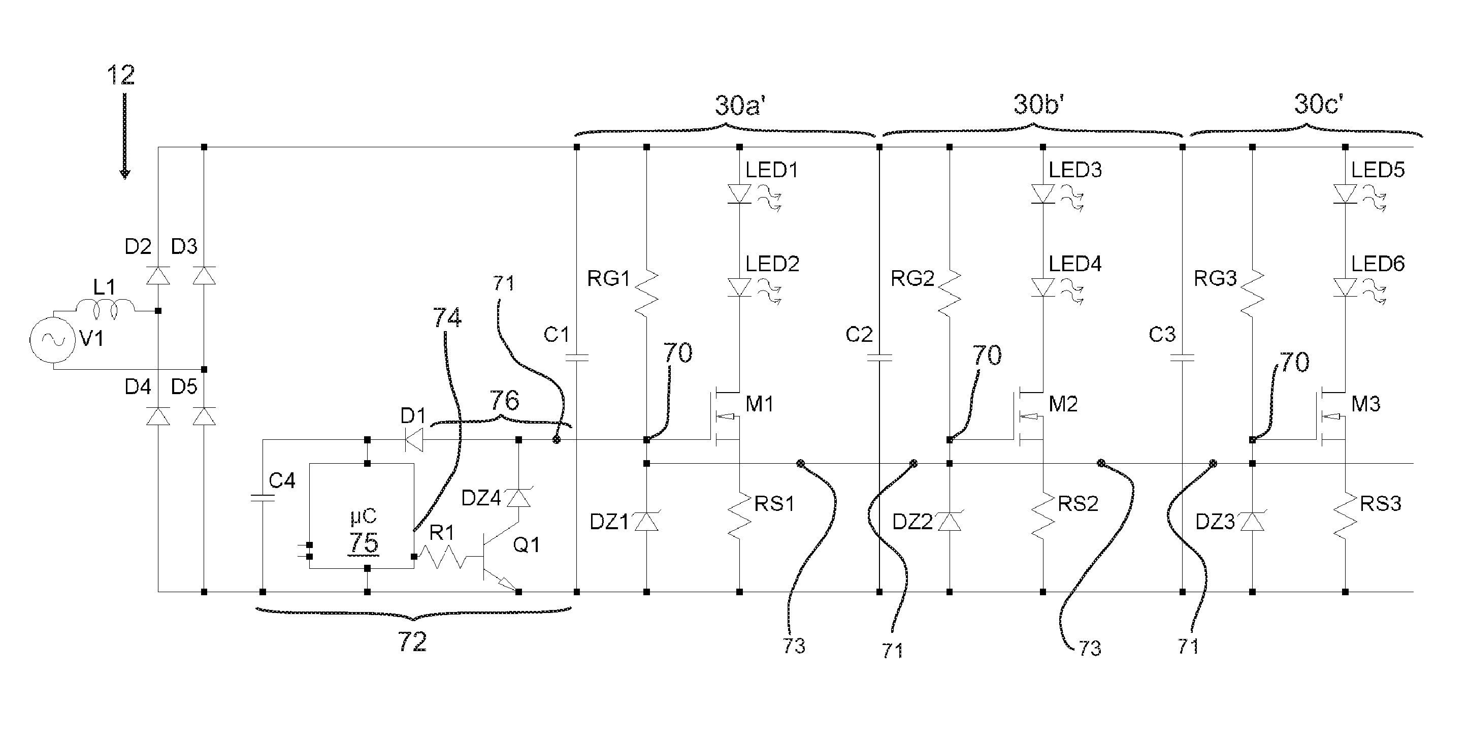
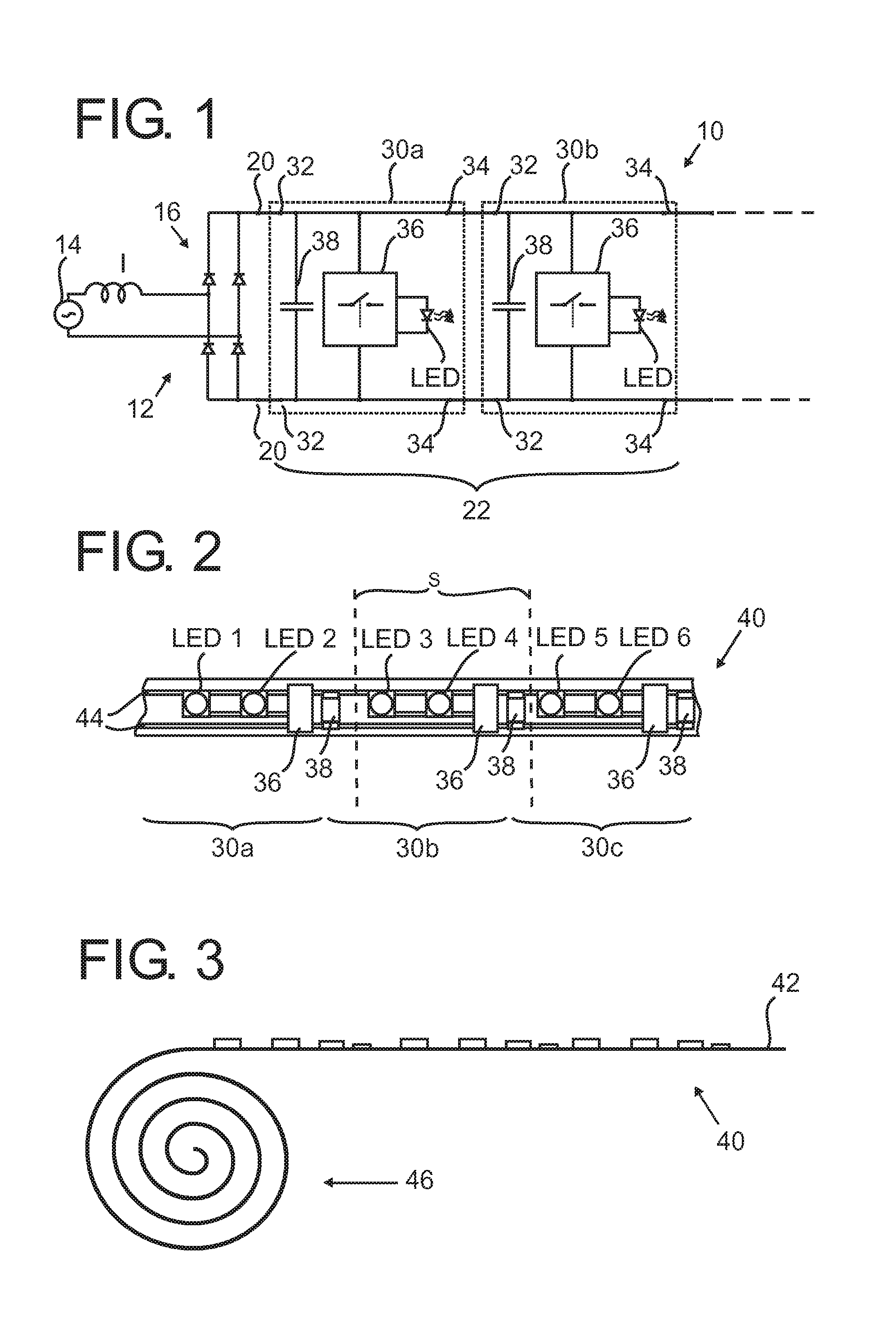
[0036]FIG. 1 shows a circuit diagram of a lighting unit 10 comprising an electrical supply unit 12 with an AC power supply 14 and, connected therewith, an inductance I and a full bridge rectifying circuit 16. The electrical supply unit 12 thus supplies DC (rectified AC) electrical power to electrical supply terminals 20 of a string 22 of identical lighting segments, of which in FIG. 1 a first lighting segment 30a and a second lighting segment 30b are shown only. The lighting segments 30a, 30b are arranged on a strip 40 as shown in FIGS. 2, 3. Each lighting segment 30a, 30b comprises segment input terminals 32, each directly connected to segment output terminals 34. All lighting segments 30a, 30b in the string 22 are connected in a sequence, such that the first lighting segment 30a is connected with segment input terminal32 to the electrical supply terminal 20, and the second lighting segment 30b and each following lighting segment is connected with its segment input terminal 32 to t...
PUM
 Abstract
Description
Claims
Application Information