
Display device and driving method thereof

a technology of a display device and a driving method, which is applied in the direction of digital storage, instruments, computing, etc., can solve the problems of affecting the operation of the display device, the distortion of the driving voltage and the gate control signal, and the delay of the data signal, so as to prevent the distortion of the gate signal

Active Publication Date: 2013-11-28
SAMSUNG DISPLAY CO LTD
View PDF6 Cites 44 Cited by
  • Summary
  • Abstract
  • Description
  • Claims
  • Application Information

AI Technical Summary

Benefits of technology

The invention relates to a display device and a method for driving it that can prevent distortion in the gate signal and compensate for signal delay in the data voltage. This results in a more uniform and accurate display across the entire panel.

Problems solved by technology

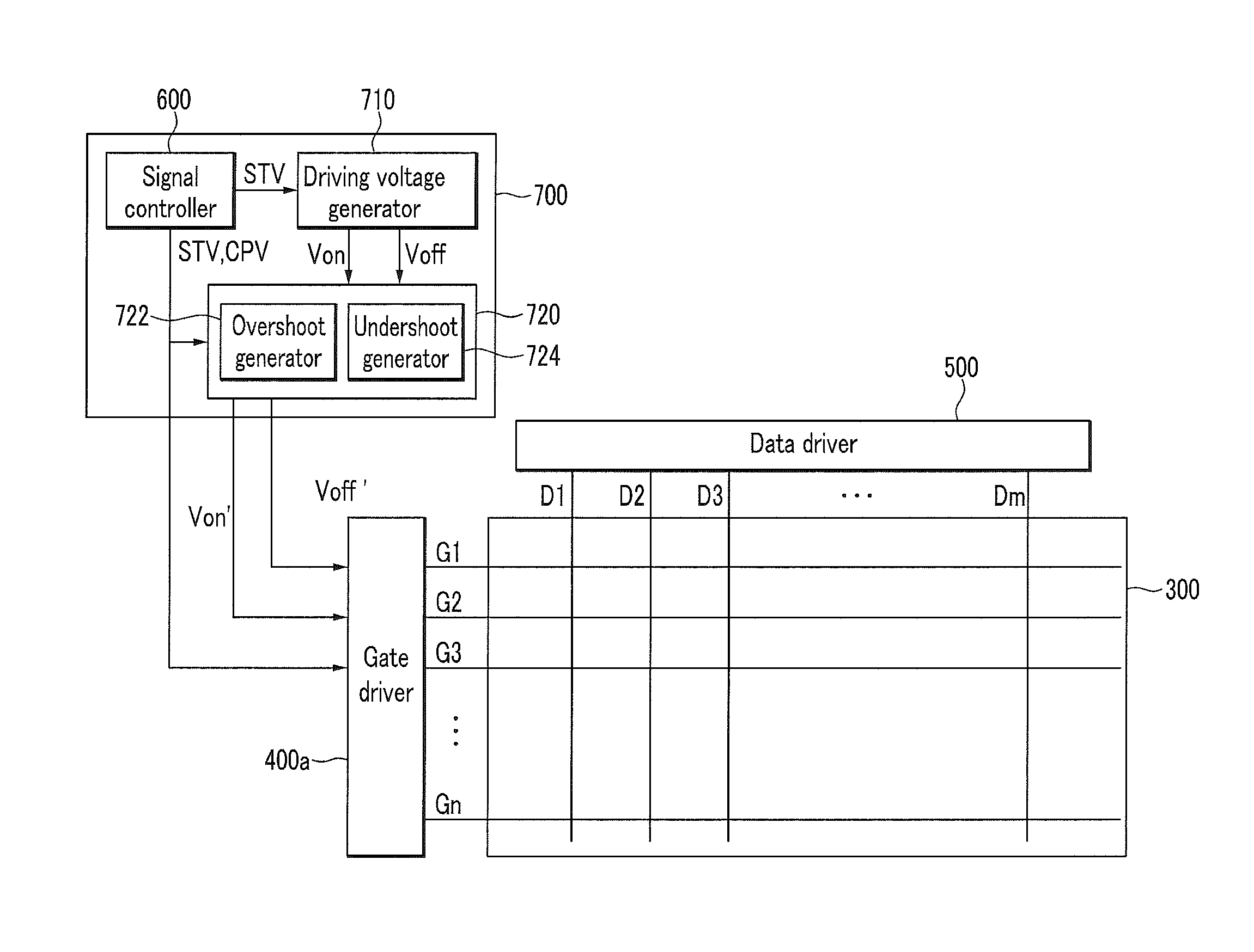
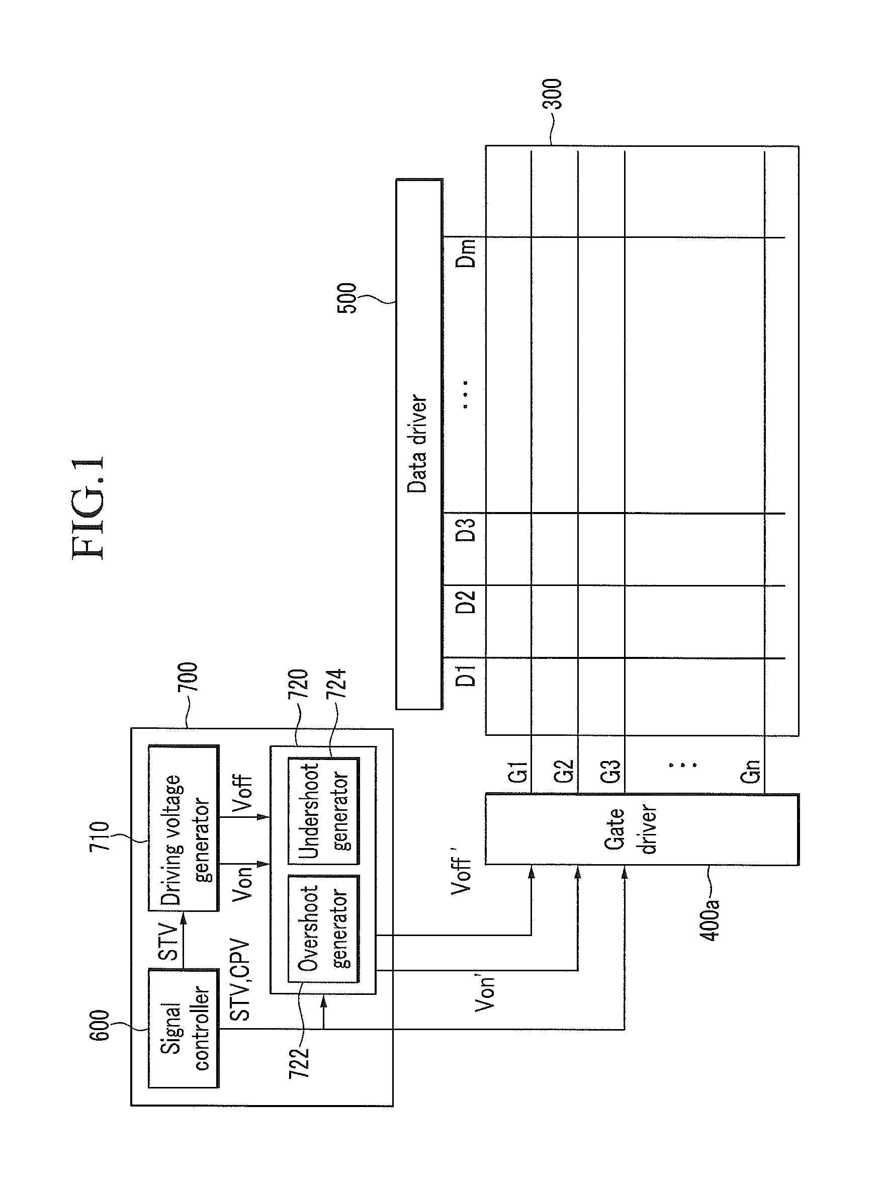
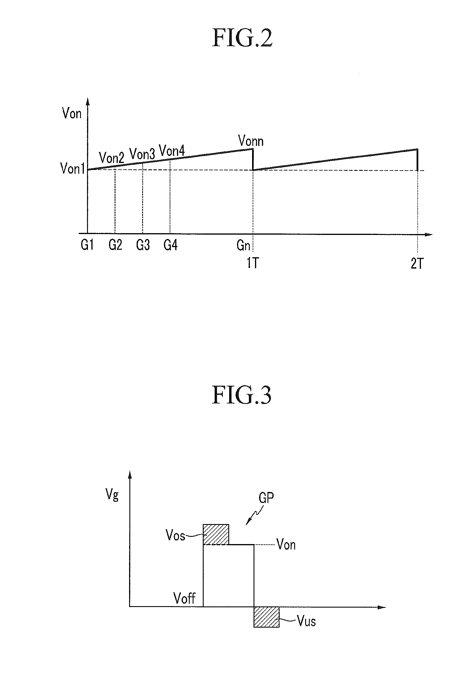
Further, a length of a signal wire that transmits a driving voltage and a gate control signal inputted to the gate driver increases as the size of the display device increases, such that the waveform of the driving voltage and the gate control signal may be distorted as being away from an input point of the signals.
Further, a length of the data line may increase as the size of the display panel increases, such that the data signal may be delayed according to the position of the display panel.

Method used


Image

  • Display device and driving method thereof
  • Display device and driving method thereof
  • Display device and driving method thereof

Examples


Embodiment Construction

[0038]The invention will be described more fully hereinafter with reference to the accompanying drawings, in which various embodiments are shown. This invention may, however, be embodied in many different forms, and should not be construed as limited to the embodiments set forth herein. Rather, these embodiments are provided so that this disclosure will be thorough and complete, and will fully convey the scope of the invention to those skilled in the art. Like reference numerals refer to like elements throughout.

[0039]It will be understood that when an element or layer is referred to as being “on”, “connected to” or “coupled to” another element or layer, it can be directly on, connected or coupled to the other element or layer or intervening elements or layers may be present. In contrast, when an element is referred to as being “directly on,”“directly connected to” or “directly coupled to” another element or layer, there are no intervening elements or layers present. Like numbers re...


PUM


Abstract

A display panel includes a plurality of gate lines and a plurality of pixels disposed thereon, a gate driver which applies a gate signal to the gate lines, and a controller which controls the gate driver, where the controller includes a signal controller which generates a scanning start signal and a gate clock signal comprising a plurality of pulses, where the scanning start signal instructs to start a scanning of the gate signal, and a driving voltage modulator which generates a modulated gate-on voltage and a modulated gate-off voltage based on a basic gate-on voltage and a basic gate-off voltage, where the driving voltage modulator adds an overshoot voltage corresponding to a rising edge of a pulse of the gate clock signal to the basic gate-on voltage or adds an undershoot voltage corresponding to a falling edge of the pulse of the gate clock signal to the basic gate-off voltage.

Description

[0001]This application claims priority to Korean Patent Application No. 10-2012-0054709 filed on May 23, 2012, and all the benefits accruing therefrom under 35 U.S.C. §119, the content of which in its entirety is herein incorporated by reference.BACKGROUND[0002](a) Field[0003]Exemplary embodiments of the invention relate to a display device including a driving device and a driving method of the display device including the driving device.[0004](b) Description of the Related Art[0005]Generally, a display device includes a plurality of pixels, which is a unit for displaying an image, and a plurality of drivers.[0006]In the display device, a plurality of pixels is connected to a plurality of gate lines and a plurality of data lines. Each of the pixels may include a switching element, such as a thin film transistor, which is connected to a gate line and a data line, and a pixel electrode connected to the gate line and the data line. The gate line and the data line may extend in differen...

Claims


Application Information

Patent Timeline
IPC IPC(8): G06F3/038
CPCG09G3/20G09G3/3266G09G3/3677G09G2310/0267G09G2310/0286G09G2310/067G09G2320/0223G11C19/28
Inventor KIM, HUN TAE
Owner SAMSUNG DISPLAY CO LTD
Learn More