Range imaging devices and methods

a range imaging and imaging device technology, applied in the field of range imaging, can solve the problems of small effect of failure of single emitter on output optical characteristics such as output power and response time, and achieve the effect of lessening the drop of output optical power

Active Publication Date: 2013-11-28
LUMENTUM OPERATIONS LLC
View PDF2 Cites 14 Cited by
  • Summary
  • Abstract
  • Description
  • Claims
  • Application Information

AI Technical Summary

Benefits of technology

[0012]According to the invention, an array of laser diode emitters on a common semiconductor substrate can be used in place of a single-emitter laser diode for redundancy. When one of the emitters fails, the remaining emitters can emit enough light to meet the output power specification. When the emitters are connected in parallel, a failure of a single emitter has a relatively small effect on the output optical characteristics such as output power and response time. The emitters are preferably disposed with a tight spacing that facilitates packaging of the entire array into a compact single package on a common heat sink. In one embodiment, the emitters are spaced in a non-uniform manner, the spacing decreasing in going from the center of the array to its edges. The non-uniform spacing can reduce thermal gradients, which helps reduce wavelength spread of individual laser diode emitters.
[0014]In accordance with another aspect of the invention there is further provided a laser diode array comprising a semiconductor substrate and a plurality of laser diode emitters on the semiconductor substrate, wherein the laser diode emitters are non-uniformly spaced along the array, the emitter spacing decreasing from the middle of the array to its edges, to reduce thermal gradients and associated emitter-to-emitter wavelength spread during operation of the array.
[0017]operating, in synchronism with the laser diode array, an optical camera for time-gated or phase-sensitive imaging of the object, to provide an object depth map from phase or time delays resulting from propagation of light emitted by the illuminator to the object and back to the optical camera.
[0018]In one embodiment, output power of the array is monitored to determine a drop of optical power due to a failure of at least one of the plurality of the emitters of the array. Upon determining the drop, the supply current is increased, so as to lessen a drop of output optical power of the array caused by the fault.

Problems solved by technology

When the emitters are connected in parallel, a failure of a single emitter has a relatively small effect on the output optical characteristics such as output power and response time.

Method used


Image

  • Range imaging devices and methods
  • Range imaging devices and methods
  • Range imaging devices and methods

Examples


Embodiment Construction

[0027]While the present teachings are described in conjunction with various embodiments and examples, it is not intended that the present teachings be limited to such embodiments. On the contrary, the present teachings encompass various alternatives, modifications and equivalents, as will be appreciated by those of skill in the art.

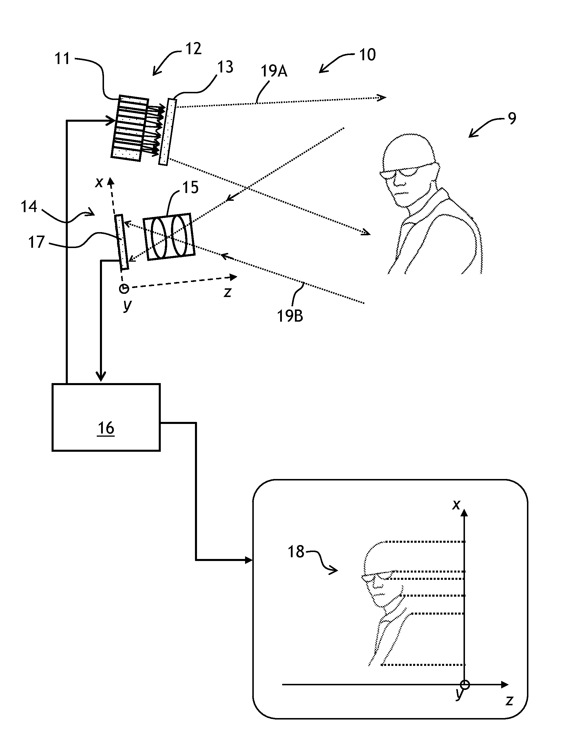
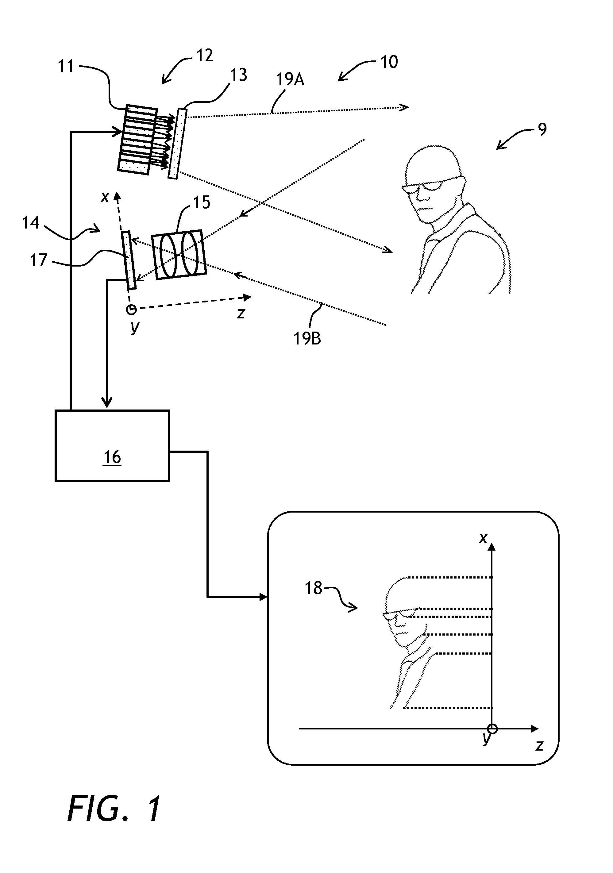
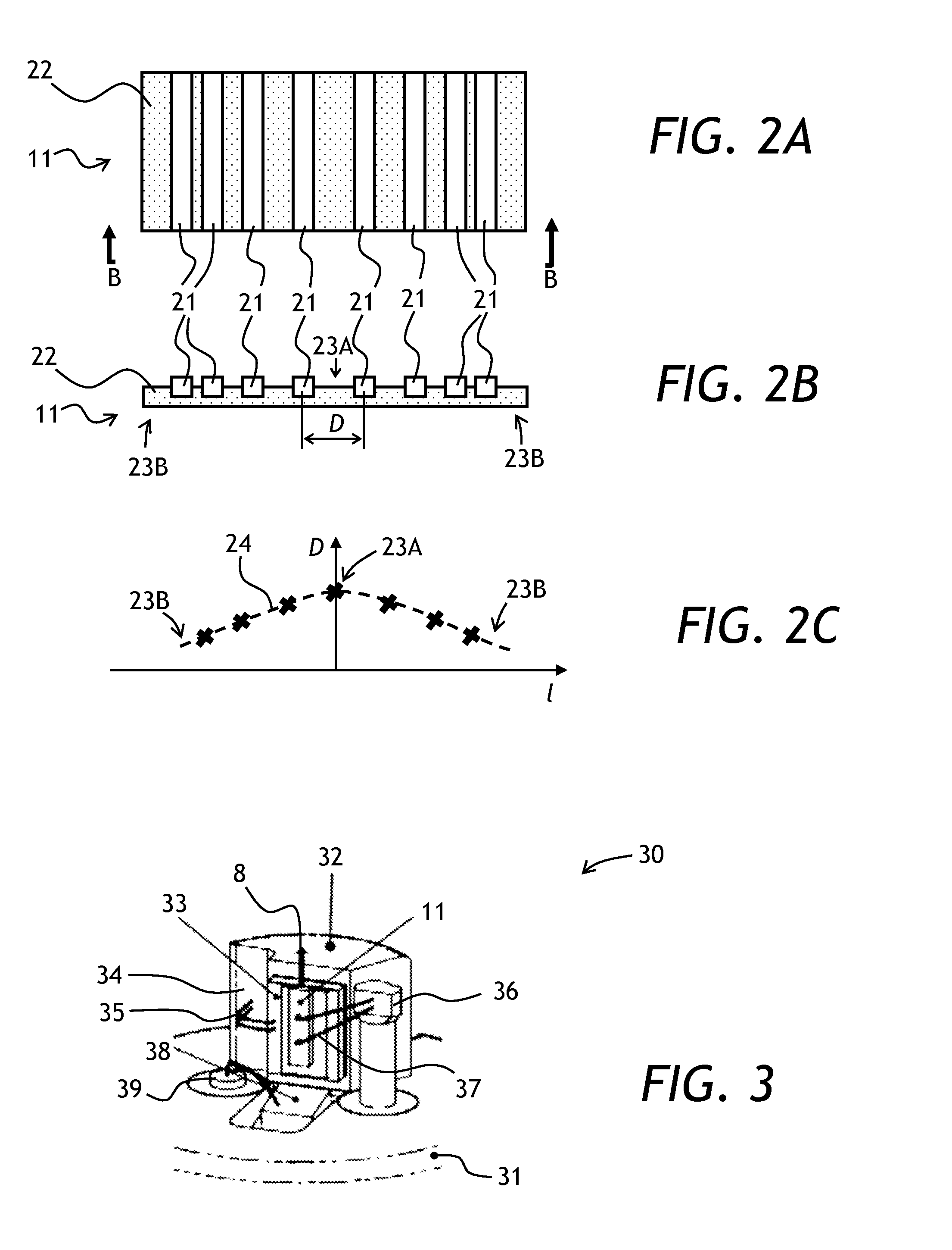
[0028]Referring to FIGS. 1, 2A, and 2B, a range imaging apparatus 10 of the invention includes an illuminator 12 and an optical camera 14. The illuminator 12 and the optical camera 14 are coupled to a controller 16. The illuminator 12 includes a laser diode array 11 and an optional diffuser 13. The diffuser 13 may have some additional functionality. By way of example, it can include an integrated Fresnel lens, no shown. A discrete lens, not shown, could also be inserted before the diffuser. The optical camera 14 includes a lens 15 and a phase-sensitive detector array 17. As seen in FIGS. 2A and 2B, the laser diode array 11 includes a plurality of laser di...


PUM


Abstract

An array of laser diode emitters is used as an illumination source for a range imaging system. The laser diode emitters are disposed on a common substrate. When one of the emitters fails, the remaining emitters emit enough light to meet the output optical power specification. The emitters can be disposed with a tight spacing. The tight spacing facilitates packaging of the entire array into a compact single package on a common heat sink.

Description

TECHNICAL FIELD[0001]The present invention relates to range imaging, and in particular to devices and methods for range imaging of an object using pulsed or modulated illumination of the object.BACKGROUND OF THE INVENTION[0002]In range imaging, each pixel of a two-dimensional image of a three-dimensional scenery is associated with information about a distance from an imaging point to a point in the scenery imaged by that pixel. In other words, each pixel includes a distance-to-object information in addition to the brightness and / or color information. Range imaging is used in applications where distance to and / or three-dimensional shape of objects being imaged needs to be determined, such as 3D profiling, gaming, human-to-computer interface, vision through fog, automotive, machine vision, etc.[0003]Range imaging is based on measuring, for every pixel of the image, of the time that it takes light to propagate from a light source to the object and back to the detector. One type of a ra...

Claims


Application Information

Patent Timeline
Patent Type & Authority Applications(United States)
IPC IPC(8): G01C3/08H01S5/40
CPCG01S13/88H01S5/02461H01S5/02469H01S5/02476H01S5/4031G01C3/08H01S5/024H01S5/0262
Inventor SKIDMORE, JAY A.ROSSIN, VICTORDOUSSIERE, PIERRE
Owner LUMENTUM OPERATIONS LLC
Why Eureka
Try Eureka