Solar concentrator

a solar concentrator and solar energy technology, applied in the field of solar concentrator design, can solve the problems of increasing the overall system weight and wind loading force, the relatively low energy conversion efficiency of solar energy generation methods, and the relatively low cost compared with other conventional energy generation methods, so as to reduce solar tracking costs, and reduce the effect of back focal distan

Active Publication Date: 2013-11-28
NAT CENT UNIV
View PDF2 Cites 3 Cited by
  • Summary
  • Abstract
  • Description
  • Claims
  • Application Information

AI Technical Summary

Benefits of technology

[0008]In view of the foregoing subject, an object of the invention is to provide a solar concentrator, which is advantageously thin and zero back focal distance so that the solar concentrator has the reduced solar tracking cost and can be adapted to various applications with limited space requirement.

Problems solved by technology

However, the solar energy technology still has some drawbacks, such as the relatively lower energy conversion efficiency and the higher cost compared with the other conventional energy generation methods.
However, the long back focal distance of the concentrating optics increases the requirement of space volume of the conventional concentrated solar energy conversion device, thereby increasing the overall system weight and wind loading force.
Therefore, the back focal distance of the solar concentrator not only increases the system space volume and the costs, but also causes the larger mounting area, and the solar energy conversion device needs the precise movement and control of the solar tracking.

Method used


Image

  • Solar concentrator
  • Solar concentrator
  • Solar concentrator

Examples


first embodiment

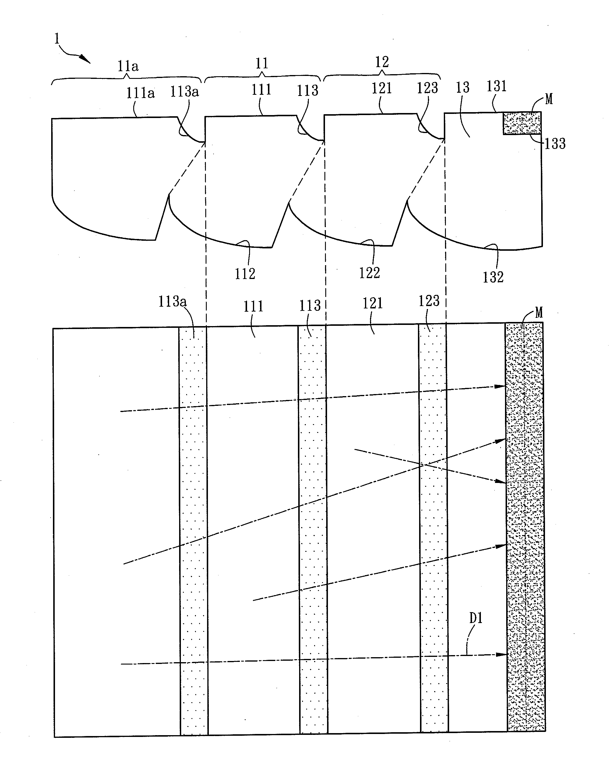
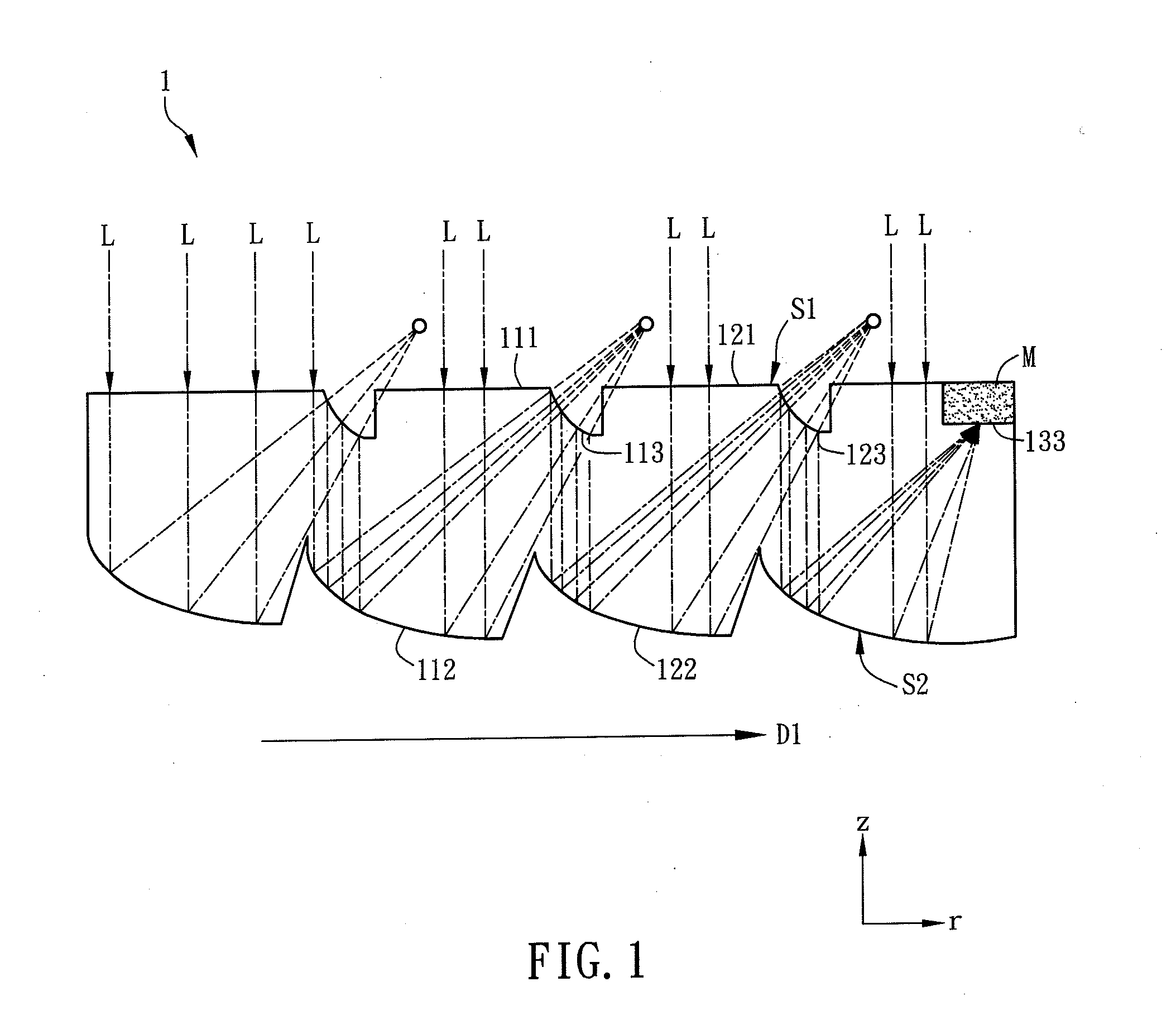
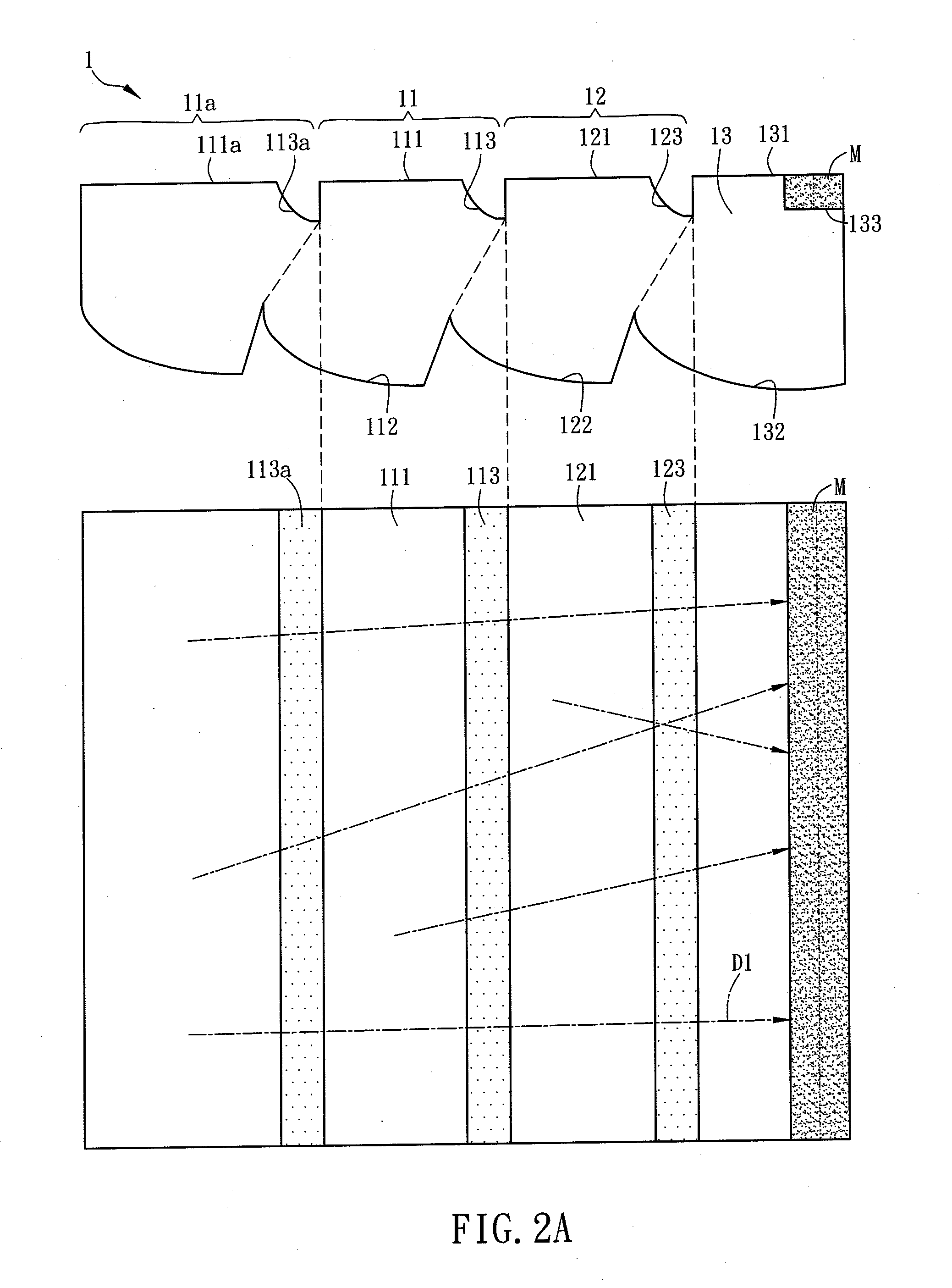
[0042]In the first embodiment, the solar concentrator 1 may further include another first light guiding module 11a. One end of the first light guiding module 11 is connected with the first light guiding module 11a, and the other end of the first light guiding module 11 is connected with the second light guiding module 12. The first light guiding module 11a may have the shape the same as or different from that of the first light guiding module 11 to facilitate the manufacturing process or to accommodate the optical design to increase the light input area of the light L. The image point of the first surface 111 and the image point of the first relay reflective surface 113a of the first light guiding module 11a are substantially coincident. In other words, light L incident to the first surface 111 is the parallel beam imaged at infinity; while the light L incident to and reflected by the first relay reflective surface 113a to is also a parallel beam imaged at infinity, so the image poi...

second embodiment

[0051]FIGS. 3A and 3B are top views showing solar concentrators according to the invention.

[0052]As shown in FIGS. 3A and 3B, the solar concentrators 2a and 2b are substantially the same as the solar concentrator 1 of the first embodiment except that the solar concentrator 1 converges the light to a lateral side thereof, while each of the solar concentrators 2a and 2b converges the light to a middle portion thereof. The light propagation destinations 233 of the solar concentrators 2a and 2b are disposed at the middle portions of the solar concentrators 2a and 2b, respectively. The light propagation destination 233 and the termination module 23a and 23b are disposed at the middle as shown in FIG. 3A or 3B, and a plurality of first light guiding modules 21a and a second light guiding module 22a are disposed at each of the opposite sides of the middle termination module 23a in a symmetrical way. Therefore, each of the solar concentrators 2a and 2b has two main light guiding directions ...

third embodiment

[0053]FIG. 4 shows top and cross-sectional views of a solar concentrator according to the invention.

[0054]Referring to FIG. 4, the solar concentrator 3 is similar to the solar concentrator 1 of the first embodiment except that the first light guiding module 31 and the second light guiding module 32 of the solar concentrator 3 have the ring shapes and are arranged in concentric circles. The light L is mainly guided to the center of the concentric circles along the radial direction D4. An opto-electronic conversion element or a heat transfer medium is disposed in the light propagation destination 333 of the termination module 33 and it is positioned at the second side S2 of the solar concentrator 3 for a better wire connectivity and environmental shielding. Of course, the light propagation destination 333 may also be disposed on the first side S1.


PUM


Abstract

A solar concentrator is composed of the cascading of the first light guiding module and a second light guiding module. The solar light is collected and guided simultaneously toward the light propagation destination by the light guiding modules. By cascading the light guiding modules in the direction of guiding, the solar concentrator has thinner thickness than the traditional concentrator and has a zero back focal distance to reduce the assembly cost. The solar concentrator utilizes the optical design concept of coincident image points from both the relay and converging optics such that the optical flux is increased in the cascading light guiding modules while the light propagation direction within the concentrator is maintained.

Description

CROSS REFERENCE TO RELATED APPLICATIONS[0001]This Non-provisional application claims priority under 35 U.S.C. §119(a) on Patent Application No(s). 101118793 filed in Taiwan, Republic of China on May 25, 2012, the entire contents of which are hereby incorporated by reference.BACKGROUND OF THE INVENTION[0002]1. Field of Invention[0003]The invention relates to a design of a solar concentrator which concentrates the solar light into a region for energy generation.[0004]2. Related Art[0005]Because the natural resources, such as the oil, coal and the like, are gradually depleted, the number of researches and development projects relating to solar energy applications are growing more rapidly than ever. However, the solar energy technology still has some drawbacks, such as the relatively lower energy conversion efficiency and the higher cost compared with the other conventional energy generation methods. So, it is an important goal to increase the utilization efficiency of the solar energy ...

Claims


Application Information

Patent Timeline
Patent Type & Authority Applications(United States)
IPC IPC(8): G02B5/10F24S23/79
CPCG02B5/10G02B19/0042G02B19/0028Y02E10/52H01L31/0543H01L31/0547F24S23/71F24S2023/87F24S23/79Y02E10/40
Inventor LIANG, CHAO-WEN
Owner NAT CENT UNIV
Why Eureka
Try Eureka