
Method for operating a resonance measuring system

a resonance measuring system and resonance technology, applied in the direction of volume flow measuring device, volume/mass flow by differential pressure, direct mass flowmeter, etc., can solve the problems of unsatisfactory, unsatisfactory, and expensive structural costs, and achieve the effect of increasing accuracy and safe allowing for ascertaining relevant measurement values or diagnostic parameters

Active Publication Date: 2013-11-28
KROHNE MESSTECHNICK GMBH & CO KG
View PDF2 Cites 10 Cited by
  • Summary
  • Abstract
  • Description
  • Claims
  • Application Information

AI Technical Summary

Benefits of technology

This patent describes a method and device for measuring the mass flow of a fluid using a Coriolis effect. The device measures the time it takes for a primary measuring signal to pass through a measuring channel, which is related to the mass flow of the fluid. The method involves transmitting the primary measuring signal through the channel and observing the behavior of the signal over time. This allows for accurate measurements and the automatic ignition of transients, reducing errors and improving accuracy.

Problems solved by technology

Stability of the measuring channels of, for example, 0.5 wad can be ensured, however, in the conventional way only by quite considerable structural and costly expense for strict compliance with reference conditions and even then only for very short periods—in the secondary range—which is, of course, unsatisfactory.

Method used


Image

  • Method for operating a resonance measuring system
  • Method for operating a resonance measuring system
  • Method for operating a resonance measuring system

Examples


Embodiment Construction

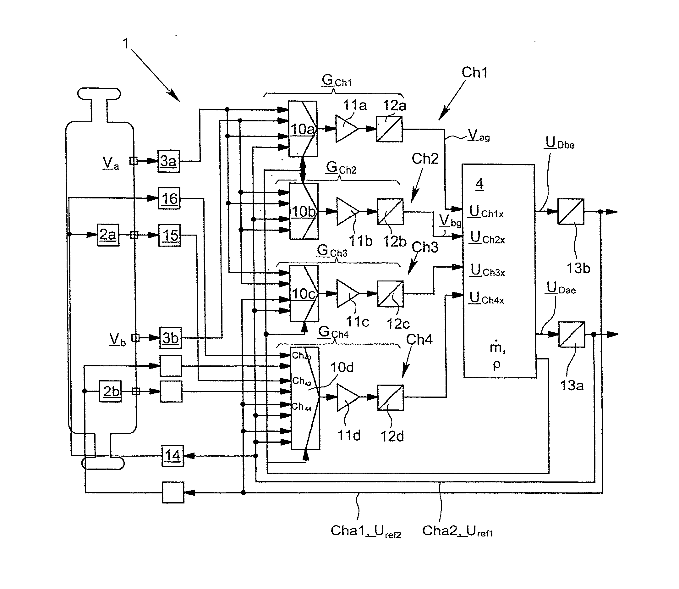
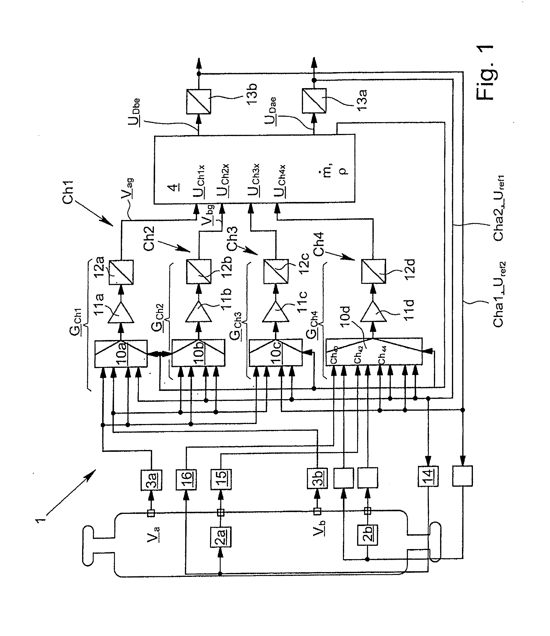
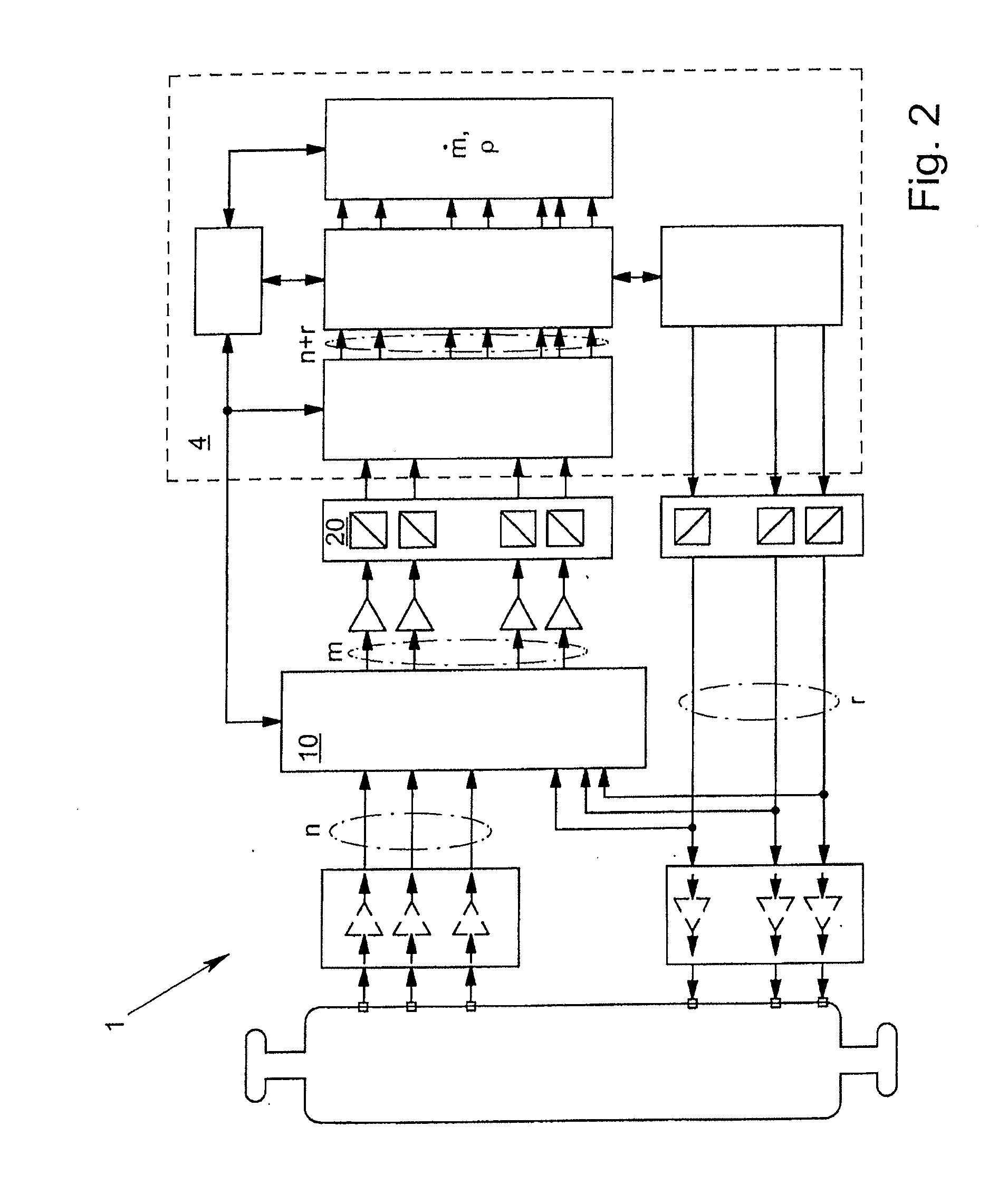
[0028]In FIGS. 1 and 2, a Coriolis mass flow measuring device 1, which—has a measuring tube (not shown) through which a medium flows and a pair of oscillation generators 2a, 2b as well as a first oscillation sensor 3a and a second oscillation sensor 3b (FIG. 1), is first shown in a very diagrammatic form. The oscillation generators 2a, 2b are formed, for example, by current-carrying coils with a permanent magnet, in such a way that when the coils are supplied with a current, a force is exerted on the measuring tube. Also, the Coriolis mass flow measuring device 1 has a control and analysis unit 4, whereby excitation signals UDae, UDbe, are generated which, in each case, are routed via an excitation channel Cha1, Cha2 to the respective oscillation generator 2a, 2b. Furthermore, the control and analysis unit 4 receives a first primary measuring signal Va of interest via a first measuring channel Ch1 from the first oscillation sensor 3a, and the control and analysis unit 4 also receive...


PUM


Abstract

A method for operating a Coriolis mass flow measuring device having at least one measuring pipe through which a medium flows, at least one vibration generator, at least a first vibration sensor, at least a second vibration sensor and at least a control and analyzing unit. The detection of measurement variables or diagnosis parameters is achieved with increased accuracy and security in that the control and analyzing unit calculates, at least indirectly and in a ratiometric manner, at least a derived secondary variable based on a primary measurement, wherein interested primary measurement signals are transmitted alternately to the control and analyzing unit via different measurement channels and wherein, based on the various values obtained from the different measurement channels regarding the primary measurement signals, compensation values of the transmitted primary measurement signals are calculated and used as a basis for the calculation of the derived secondary variable.

Description

BACKGROUND OF THE INVENTION[0001]1. Field of the Invention[0002]The invention relates to a method for operating a Coriolis mass flow measuring device, whereby the Coriolis mass flow measuring device has at least one measuring tube through which a medium flows, at least one oscillation generator, at least one first oscillation sensor, at least one second oscillation sensor, and at least one control and analysis unit, whereby excitation signals can be routed to the oscillation generator from the control and analysis unit via at least one excitation channel, whereby a first primary measuring signal of interest can be routed to the control and analysis unit from the first oscillation sensor via at least one first measuring channel, and a second primary measuring signal of interest can be routed to the control and analysis unit from the second oscillation sensor via at least one second measuring channel. Moreover, the invention also relates to a Coriolis mass flow measuring device, with ...

Claims


Application Information

Patent Timeline
IPC IPC(8): G01F1/84G01F25/00
CPCG01F1/84G01F25/0007G01F1/8431G01F1/8436G01F25/10
Inventor KOLAHI, KOUROSHSTORM, RALFPOREMBA, ANDREAS
Owner KROHNE MESSTECHNICK GMBH & CO KG
Learn More