Battery pack mounting structure for electric vehicle

a technology for electric vehicles and battery packs, applied in the direction of electric propulsion mounting, transportation and packaging, propulsion parts, etc., can solve the problems of limited battery capacity, difficult to ensure the sufficient amount of battery capacity, and inability to make a space below the vehicle interior, etc., to achieve the effect of increasing the number of battery modules and not lowering the rigidity of the rear par

Active Publication Date: 2013-12-05
SUZUKI MOTOR CORP
View PDF4 Cites 10 Cited by
  • Summary
  • Abstract
  • Description
  • Claims
  • Application Information

AI Technical Summary

Benefits of technology

[0008]It is therefore an object of the present invention to increase the number of battery modules to be mounted on a vehicle in which a battery pa

Problems solved by technology

Therefore, it is not possible to make a space below the vehicle interior for mounting a large-sized battery pack therein.
Consequently, there is a problem that the battery capacity is limited.
However, since it is necessary to make a shock absorption space behind the battery pack, there still remains a proble

Method used


Image

  • Battery pack mounting structure for electric vehicle
  • Battery pack mounting structure for electric vehicle
  • Battery pack mounting structure for electric vehicle

Examples


Embodiment Construction

[0020]Reference will now be made in detail to the present embodiments of the present invention, examples of which are illustrated in the accompanying drawings, wherein like reference numerals refer to the like elements throughout. The embodiments are described below in order to explain the present invention by referring to the figures.

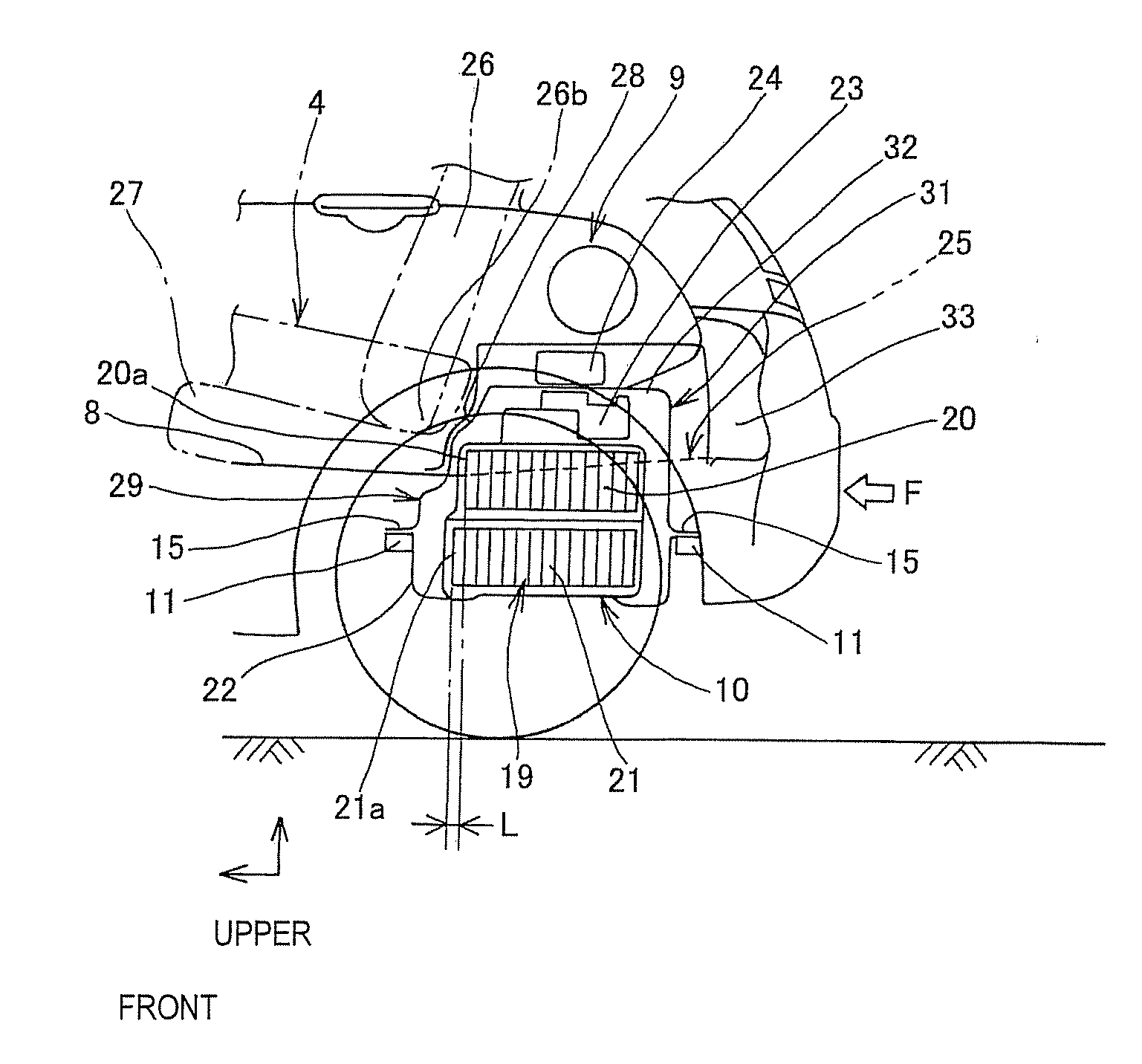
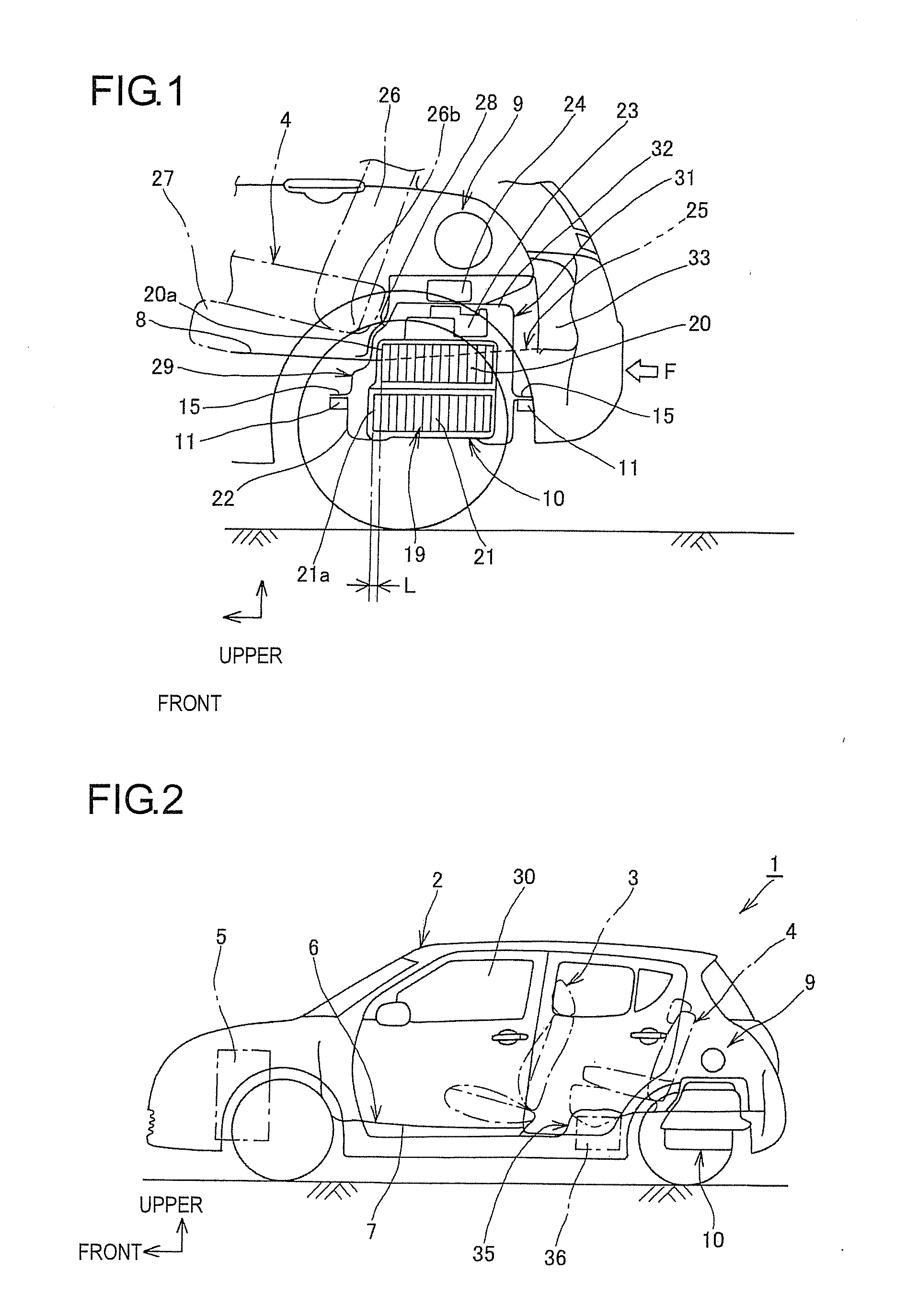
[0021]Hereinafter, an exemplary embodiment of the present invention will be described with reference to the drawings. FIGS. 1 to 6 illustrates an exemplary embodiment of the present invention. As shown in FIG. 2, an electric vehicle 1 (including a hybrid electric vehicle) includes a vehicle body 2, a front seat 3 and a rear seat 4. In the electric vehicle 1, an engine 5 for power generation is mounted in a front part of the vehicle and a floor panel 6 is disposed below a vehicle interior (a passenger compartment). The floor panel 6 has a front floor 7 that extends from a lower part of the front seat 3 to a front part of the rear seat 4 and a rear floor...


PUM


Abstract

There is provided a battery pack mounting structure for an electric vehicle. A battery pack is mounted in a space behind a rear seat of the electric vehicle. Battery modules are accommodated in the battery back are in a stacked state in a height direction of the electric vehicle. A floor panel behind the rear seat is formed with an opening into which an upper part of the battery pack is inserted. When seen from a side of the electric vehicle, a dimension of one battery module disposed at a position protruding upwards from the opening, is smaller in the longitudinal direction than that of another battery module disposed below the one battery module, and a front end portion of the one battery module is offset towards a rear side of the electric vehicle relative to that of the another battery module.

Description

CROSS-REFERENCE TO RELATED APPLICATIONS[0001]This application claims the benefit of Japanese Application No. 2012-127813, filed Jun. 5, 2012, in the Japanese Intellectual Property Office, the disclosures of which are incorporated herein by reference.BACKGROUND OF THE INVENTION[0002]1. Field of the Invention[0003]The present invention relates to a battery pack mounting structure for an electric vehicle, and more particularly, to a battery pack mounting structure for an electric vehicle capable of increasing the number of battery modules to be mounted on a vehicle in which a battery pack accommodating the battery modules therein is arranged in a space behind a rear seat without lowering the rigidity of a rear part of the vehicle.[0004]2. Description of the Related Art[0005]In an electric vehicle including a hybrid electric vehicle, a secondary battery is mounted on a vehicle and the vehicle can travel with a driving motor. The maximum traveling distance of the electric vehicle with th...

Claims


Application Information

Patent Timeline
IPC IPC(8): B60K1/04
CPCB60K1/04B60K2001/0416B60K2001/0438Y10S903/907Y02E60/10
Inventor NITAWAKI, KUNIHIRO
Owner SUZUKI MOTOR CORP
Why Eureka
Try Eureka