Household appliance having a warming drawer with a thermally conductive layer

a technology of thermal conductivity and heating drawers, which is applied in the direction of heating types, domestic stoves or ranges, furnaces, etc., can solve the problems of difficult assembly and repair work of components of such a warming drawer, complex and time-consuming assembly of parts of the warming drawer within the warming drawer housing during manufacturing, and improve thermal contact. , the effect of accurate determination of a true temperatur

Active Publication Date: 2013-12-05
BSH HOME APPLIANCES CORP
View PDF31 Cites 16 Cited by
  • Summary
  • Abstract
  • Description
  • Claims
  • Application Information

AI Technical Summary

Benefits of technology

[0004]The present invention is directed to a warming drawer having a thermally conductive layer between the sensor of a thermostat and the underside of a heating element, thereby improving thermal contact between the sensor and the underside of the heating element and ensuring an accurate determination of a true temperature of the heating element by the thermostat. In this way, the present invention can provide simple, easy to manufacture, and inexpensive means for improving the thermal conductivity between a thermostat and an underside of the heating element, which may ensure that a power supply to the heating element can be interrupted or shut off in time to prevent damage or overheating if a temperature exceeds a predetermined threshold, or that an accurate and true temperature can be provided by the thermostat to a control unit such that the control unit accurately can control the operation of the heating element. The exemplary embodiments also may simplify the manufacturing process and reduce an amount of labor, time, and manufacturing costs by providing a single sheet that covers the entire plate and / or providing adhesive on one or both side of the heat conductive sheet, film, or tape. The exemplary embodiments also may provide an additional advantage of eliminating a need for other insulation means between the support plate and the heating element.

Problems solved by technology

The conventional warming drawer having a heating element fixed to the interior of the housing and the warming drawer moving over the heating element when the warming drawer is moved to a closed position may have limited or reduced heat transfer between the heating elements and the warming drawer and the contents of the warming drawer and the heat transfer may vary for different positions in the drawer, thereby resulting in hot spots in the drawer.
Assembly and repair work for components of such a warming drawer commonly may be difficult to perform particularly where the appliance is installed in cabinetry.
The assembly of the parts of the warming drawer within the warming drawer housing during manufacturing also can be complex and time-consuming.

Method used


Image

  • Household appliance having a warming drawer with a thermally conductive layer
  • Household appliance having a warming drawer with a thermally conductive layer
  • Household appliance having a warming drawer with a thermally conductive layer

Examples


Embodiment Construction

[0041]The present invention now is described more fully hereinafter with reference to the accompanying drawings, in which embodiments of the invention are shown. This invention may, however, be embodied in many different forms and should not be construed as limited to the embodiments set forth herein; rather, these embodiments are provided so that this disclosure will be thorough and complete, and will fully convey the scope of the invention to those skilled in the art.

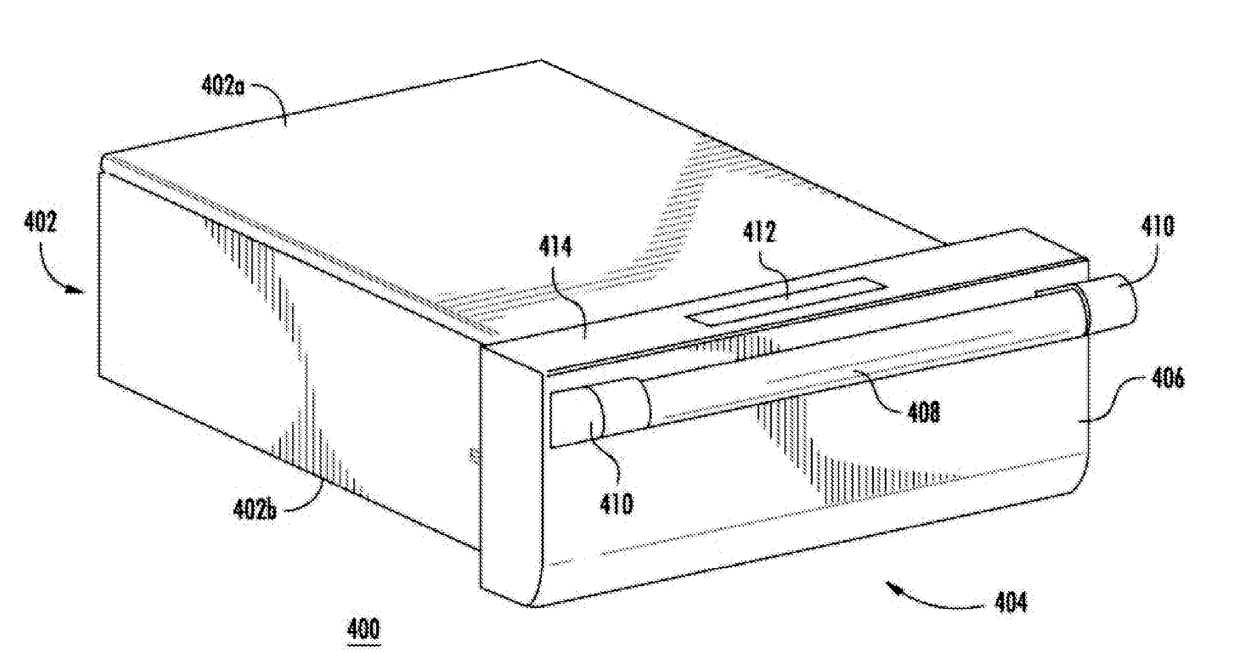
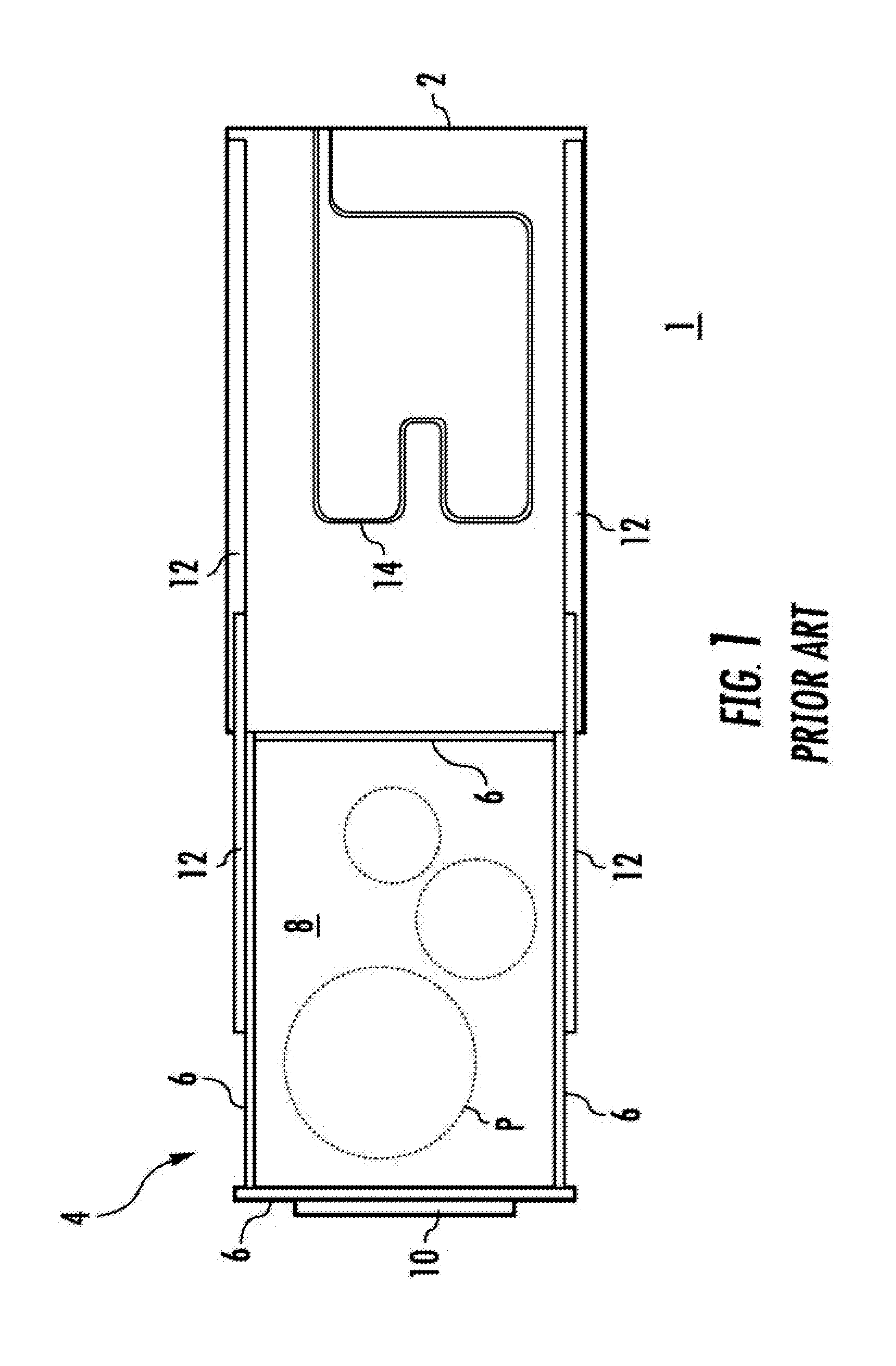
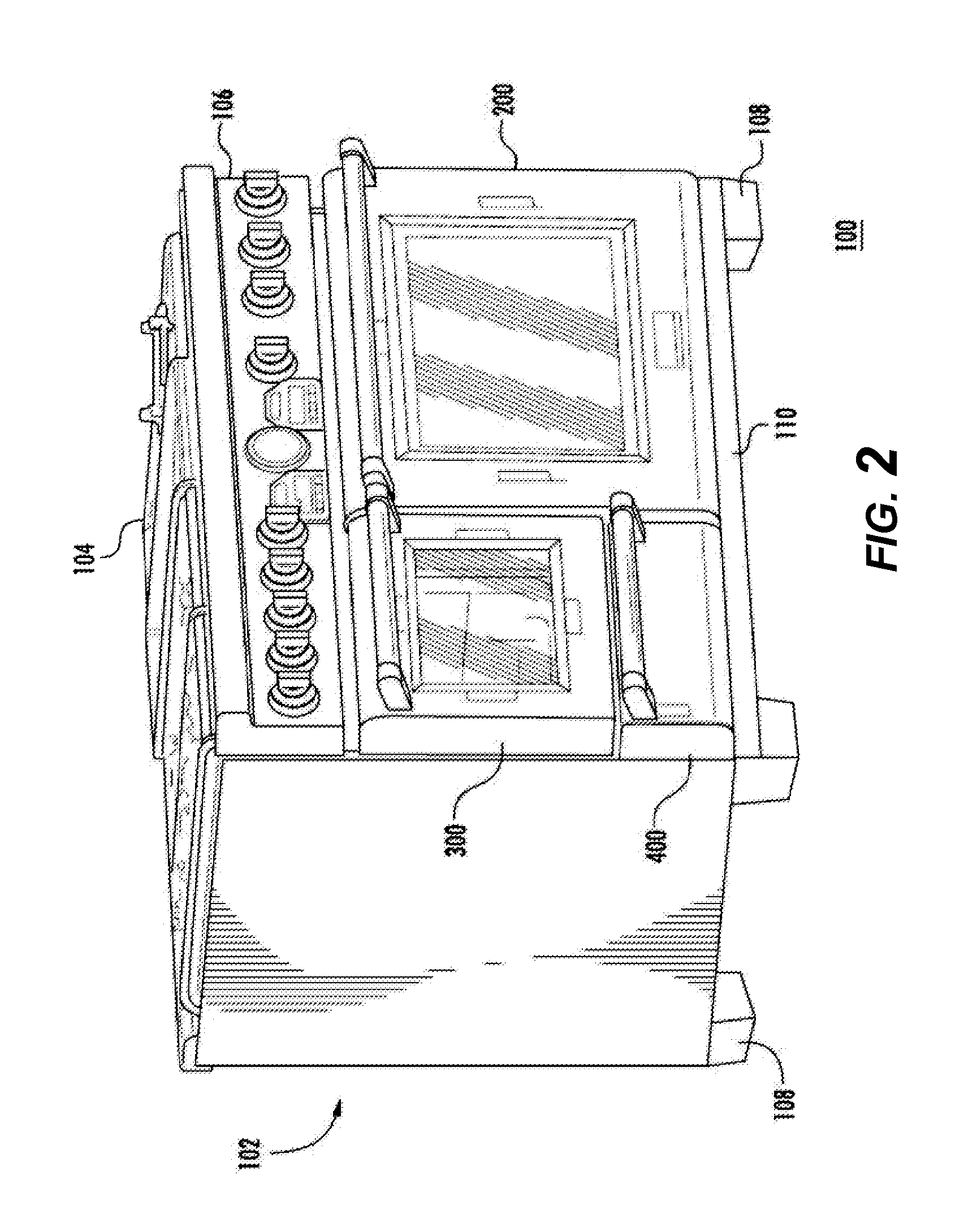
[0042]Referring now to the drawings, FIGS. 2-15C illustrate exemplary embodiments of a household appliance having a thermally conductive layer under a glass heating element of a warming drawer. Prior to describing the exemplary embodiments of the thermally conductive layer in greater detail, and to provide a better understanding of the invention, this disclosure will first describe an exemplary warming drawer assembly that derives particular advantages from the thermally conductive layer according to the present inven...


PUM


Abstract

A household appliance includes a warming drawer housing having an interior chamber and a warming drawer module in the interior chamber. The warming drawer module includes a glass heating element forming a floor surface of the warming drawer module for receiving items to be warmed, a thermostat having a sensor measuring a temperature of the glass heating element, the thermostat being disposed under the glass heating element, and a thermally conductive layer disposed between an underside of the glass heating element and the sensor of the thermostat.

Description

CROSS-REFERENCES TO RELATED APPLICATIONS[0001]This application is related to Applicants' co-pending U.S. applications, which are filed concurrently herewith, entitled “HOUSEHOLD APPLIANCE HAVING A DEPLOYABLE WARMING DRAWER MODULE”, Attorney Docket No. 2011P04309US; “HOUSEHOLD APPLIANCE HAVING A DRIP GUARD FOR A WARMING DRAWER”, Attorney Docket No. 2011P04311US; “HOUSEHOLD APPLIANCE HAVING A THERMOSTAT RETAINER FOR A THERMOSTAT OF A WARMING DRAWER”, Attorney Docket No. 2011P04547US; “HOUSEHOLD APPLIANCE HAVING EMBOSSES SUPPORTING A GLASS HEATING ELEMENT OF A WARMING DRAWER”, Attorney Docket No. 2011P04626US, each of which is incorporated herein by reference in its entirety.FIELD OF THE INVENTION[0002]The present invention is directed to a household appliance having a warming drawer, and more particularly, to a household appliance having a thermally conductive layer under a glass heating element of a warming drawer.BACKGROUND OF THE INVENTION[0003]Some conventional household appliance...

Claims


Application Information

Patent Timeline
Patent Type & Authority Applications(United States)
IPC IPC(8): F24C7/00
CPCF24C15/18F24C15/105H05B3/265A47J39/006F24C7/00
Inventor BRINGE, WILLIAMHARWARD, SAMUELWARF, BENJAMIN
Owner BSH HOME APPLIANCES CORP
Why Eureka
Try Eureka