Reactor

a technology of reactors and iron cores, applied in the field of reactors, can solve the problems of increasing the cost required for materials and processing, and the cost reduction alone is not enough, and achieves the effect of reducing the cost required

Active Publication Date: 2013-12-05
DENSO CORP
View PDF0 Cites 4 Cited by
  • Summary
  • Abstract
  • Description
  • Claims
  • Application Information

AI Technical Summary

Benefits of technology

[0016]According to a reactor of the present invention, it becomes possible to reduce cost required for materials and processing in comparison with reactors using an iron core with laminated electromagnetic steel plates or a compound magnetic core, while ensuring specific specifications for electric vehicles such as HVs by arranging a reactor to include a reactor core which is configured to have an annular shape by arranging a pair of substantially U-shaped core members, each having two leg portions and each being made from Fe—Si system magnetic powder as one body, to oppose each other via two intervening gaps; and coils which are wound around leg portions of each of the core members opposing each other via the intervening gaps.

Problems solved by technology

The iron core of the above Patent Document 1 has a disadvantage of increased cost required for materials and processing because the iron core strips are formed by laminating electromagnetic steel plates.
This disadvantage can also be found in the compound magnetic core reactor of the above Patent Document 2 in which magnetic cores made up of different materials, namely, a ferrite magnetic core and a pressurized powder magnetic core, are combined.
Further, for a reactor of a boost converter mounted on an electric vehicle such as HV, aiming at cost reduction alone is not enough.

Method used


Image

  • Reactor
  • Reactor
  • Reactor

Examples


Embodiment Construction

[0030]Embodiments according to the present invention (hereinafter referred to as “embodiments”) are described in detail below by referring to the attached drawings. The specifics such as shapes, materials, numerals, and directions in the description are presented merely for facilitating understanding of the present invention and are changeable in accordance with usages, purposes, specifications, or the like.

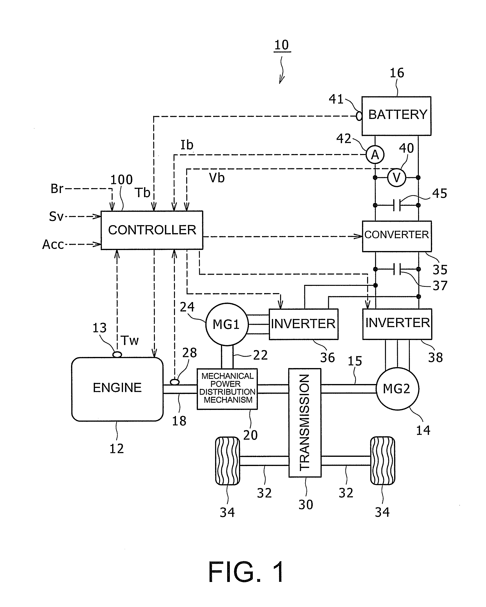
[0031]Although a hybrid vehicle provided with two motor generators (rotary electric machines), each having a motor function and a power generation function, is described below, such a structure is provided merely as an example. A hybrid vehicle may include one motor with a motor function alone and the other motor with a power generation function alone, or alternatively, one motor generator only, or three or more motor generators. Further, although a hybrid vehicle provided with an engine and a motor as power sources is described below as an example, the present invention may be a...


PUM

PropertyMeasurementUnit
total lengthaaaaaaaaaa
cross-sectional areaaaaaaaaaaa

Abstract

A reactor, which enables costs to be reduced while ensuring specific specifications for an electric vehicle such as an HV vehicle, is provided. The reactor for an HV vehicle includes: a reactor core in which a pair of roughly U-shaped core members, which have been integrally formed using an Fe—Si magnetic powder, are arranged in a circular shape by aligning two leg sections of each core member opposite to each other with gaps therebetween; and coils wound around the periphery of the leg sections of the core members, which are positioned opposite to each other with the gaps therebetween.

Description

TECHNICAL FIELD[0001]The present invention relates to reactors, in particular to a reactor used for a converter in an electric vehicle which includes a rotary electric machine as an output source of power, a power supply for supplying driving electrical power to the rotary electric machine, and a converter for converting DC voltage supplied from the power supply and outputting the converted voltage to the rotary electric machine.BACKGROUND ART[0002]Hybrid vehicles (hereinafter also referred to as “HV”) mounted with an engine and a motor as power sources are known. HVs are provided with a DC power supply such as a rechargeable secondary cell. HVs drive the motor by electrical power supplied from the DC power supply. In this case, in order to improve running performance of the vehicle, a boost converter may be used as a boosting device which boosts the DC voltage from the DC power supply and supplies the boosted voltage to the motor.[0003]A boost converter for an HV generally includes...

Claims


Application Information

Patent Timeline
Patent Type & Authority Applications(United States)
IPC IPC(8): H01F27/255
CPCH01F27/255H01F1/24H01F3/14H01F37/00
Inventor SHINOHARA, NOBUKI
Owner DENSO CORP
Why Eureka
Try Eureka