

Light source device and image display apparatus
a light source device and image display technology, applied in the field of light source devices and image display devices, can solve the problems of reducing light utilization efficiency, reducing the size of the optical system of the light source device, and increasing the number of optical parts, so as to reduce the size and the number of parts
- Summary
- Abstract
- Description
- Claims
- Application Information
AI Technical Summary
Benefits of technology
Problems solved by technology
Method used
Image

Examples
first embodiment
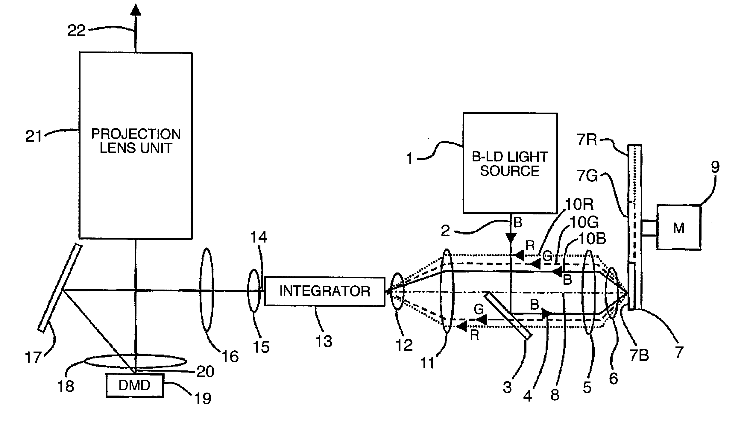
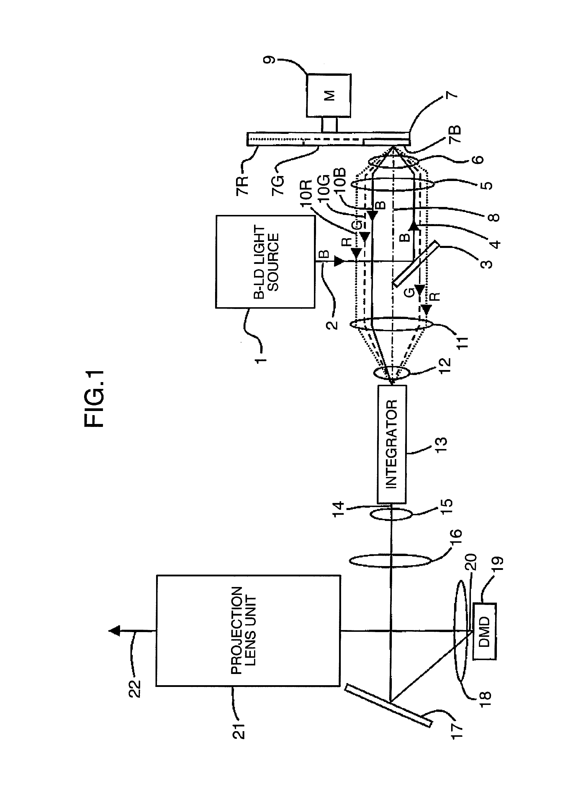
[0023]FIG. 1 shows, in a top view, main sections of a light source device and an image display apparatus in a first embodiment according to the present invention.
[0024]Substantially collimated blue (B) light 2 from a blue laser diode (B-LD) light source 1 enters a dichroic mirror 3. Hereinbelow, the blue laser diode is abbreviated as B-LD and blue is abbreviated as B. The B-LD light source 1 includes a plurality of B-LD, not shown. The dichroic mirror 3 has a spectral transmissive reflectivity characteristic to reflect B light and to transmit green (G) light and red (R) light. Hereinbelow, green is abbreviated as G and red is abbreviated as R.
[0025]B light 4 reflected by the dichroic mirror 3 is refracted through a lens 5 and a lens 6 to be focused substantially onto one point and then enters a color wheel 7.
[0026]In this configuration, the lenses 5 and 6 have a shared optical axis 8, and the B light 4 transmits substantially the lower-half section below the optical axis 8 in FIG. 1...
second embodiment
[0039]Next, description will be given of the second embodiment of the present invention.
[0040]FIG. 3 is a top view showing main sections of a light source device and an image display apparatus in the second embodiment. In FIG. 3, the same reference numerals as those of FIGS. 1 and 2 represent the same constituent components.
[0041]Substantially collimated B light 2 from the B-LD light source 1 enters a dichroic mirror 23a. The dichroic mirror 23a has a spectral transmissive reflectivity characteristic to transmit B light and to reflect G light and R light.
[0042]B light 4 transmitted through the dichroic mirror 23a is refracted by the lenses 5 and 6 to be focused substantially onto one point and then enters the color wheel 7.
[0043]The lenses 5 and 6 have a shared optical axis 8, and the B light 4 transmits through substantially the right-half section with respect to the optical axis 8 in FIG. 1. That is, the dichroic mirror 23a is disposed in substantially the right-half section with ...
third embodiment
[0058]Next, description will be given of the third embodiment of the present invention.
[0059]FIG. 4 is a top view showing main sections of a light source device and an image display apparatus in the third embodiment.
[0060]Substantially collimated B light 2 from the B-LD light source 1 enters a dichroic mirror 24a. The dichroic mirror 24a has a spectral transmissive reflectivity characteristic to transmit B light, to reflect G light, and to transmit R light.
[0061]B light 4 transmitted through the dichroic mirror 24a is refracted by the lenses 56 to be focused substantially onto one point and then enters the color wheel 25.
[0062]The lenses 5 and 6 have a shared optical axis 8, and the B light 4 transmits through substantially the right-half section with respect to the optical axis 8 in FIG. 4. That is, the dichroic mirror 24a is disposed in substantially the right-half section with respect to the optical axis 8 in FIG. 4.
[0063]FIG. 5 is a top view of the color wheel 25 of the third em...
PUM
 Abstract
Description
Claims
Application Information