Methods and Systems for Microseismic Mapping

a technology of microseismic mapping and detection methods, applied in the field of methods and systems for detection and analysis of seismic waveform data, can solve the problems of inability to realize real-time operation, unstable and unreliable steps, and inability to accurately locate the even

Inactive Publication Date: 2013-12-05
SCHLUMBERGER TECH CORP
View PDF2 Cites 10 Cited by
  • Summary
  • Abstract
  • Description
  • Claims
  • Application Information

AI Technical Summary

Problems solved by technology

These approaches have been applied to individual sensor channels and hence have tended to be unstable and unreliable in the presence of significant noise.
Accordingly, intervention, pick verification, and manual pick adjustment have often been required, but those steps are time consuming and do not permit real-time operation.
However, the CMM technique as described above has some inherent drawbacks, including that it has not provided standard measures of localization uncertainty which in the past have been computed from the measurement versus model residuals associated with discrete time picks, and that the assumed geometries cause the accuracy of the above approach to break down as wellbore deviation increases and events move away from the target plane.
The CMM technique may also encounter drawbacks for multi-well data acquisition, where the ability to handle an arbitrarily distributed receiver network is preferred.
The limitations of conventional waveform data processing techniques noted in the preceding are not intended to be exhaustive but rather are among many which may reduce the effectiveness of previously known techniques.

Method used


Image

  • Methods and Systems for Microseismic Mapping
  • Methods and Systems for Microseismic Mapping
  • Methods and Systems for Microseismic Mapping

Examples


example

Real Dataset

[0128]A hydraulic fracturing monitoring took place in Far East Asia from a deviated well. Due to constraints associated to high temperature, only three 3C receivers were deployed between 3800 m and 3925 m where the well deviation was around 30°. During the first stage of heavy brine injection, about 300 events were detected; while during the second injection stage of light brine, about 400 events were detected.

[0129]Using the 2D approach, the times were not well estimated and the events were on average located 250 m shallower than the locations found using time picks and the Geiger method (Table 3 below). The 2D origin time and spatial coordinates were significantly different from those of the Geiger approach. For instance, for the event presented in FIG. 13, the origin time was estimated at 146 ms and the coordinates were: North: −899 m; Easting: 1175 m; Elevation: −4066 m whereas using the Geiger method the estimates were: 131 ms; −917 m+ / −34; 983 m+ / −25 m; −4902 m+ / −8...


PUM


Abstract

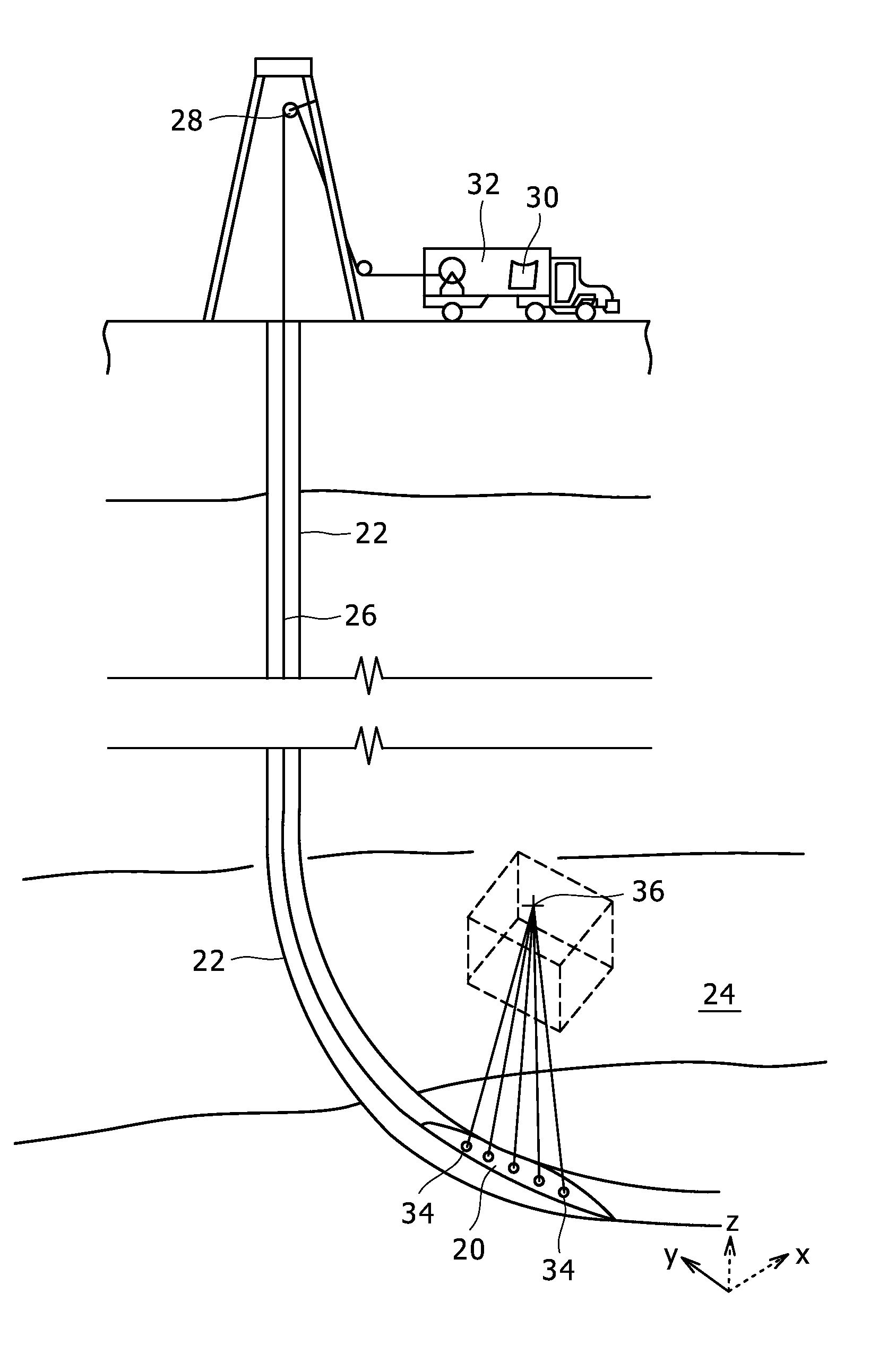
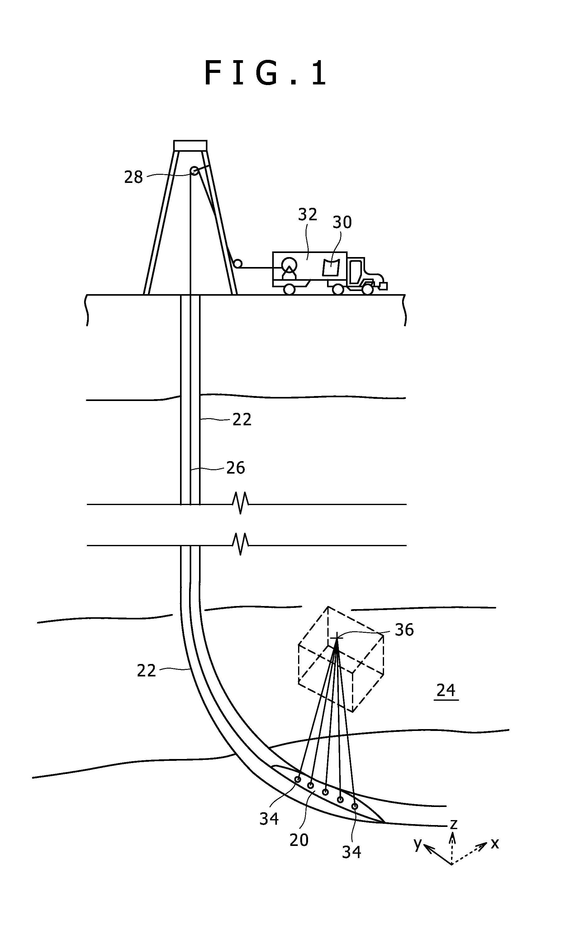
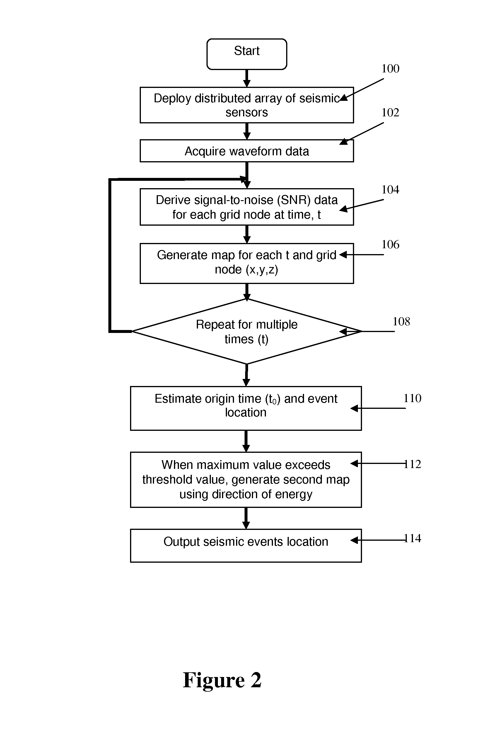
Methods and systems for the detection and localization of microseismic events are proposed which operate in real-time. Hypocenters in three spatial dimensions are provided along with an estimate of the event origin time. Sensor positions may be distributed in 3D space, and are not confined to linear arrays in vertical wells. A location of the event is approximated and a grid search, based on the approximate location of the event, is used to derive a residual function over a finer sampling followed by a gradient search of the residual function to optimize the location of the event.

Description

CROSS REFERENCE TO RELATED APPLICATIONS[0001]This application is a divisional application of co-pending U.S. patent application Ser. No. 12 / 756,195, filed on Apr. 8, 2010 which is continuation-in-part application of co-pending U.S. patent application Ser. No. 12 / 420,061, filed Apr. 8, 2009, the content of which is incorporated herein by reference for all purposes.BACKGROUND OF THE DISCLOSURE[0002]1. Field of the Invention[0003]The present disclosure relates to methods and systems for detection and analysis of seismic waveform data and, more particularly, methods and systems for the real-time 3D detection of microseismic events usable in non-vertical boreholes.[0004]2. Background of the Related Art[0005]A reliable real-time scheme for the detection / localization of microseismic events is important for Hydraulic Fracture Monitoring (HFM) and Reservoir Monitoring (RM), to enable timely decision making during stimulation operations and for reservoir management, among other applications. ...

Claims


Application Information

Patent Timeline
Patent Type & Authority Applications(United States)
IPC IPC(8): G01V1/28
CPCG01V1/288G01V2210/123G01V1/303G01V1/40
Inventor KHADHRAOUI, BASSEMLESLIE, DAVIDMICHAUD, GWENOLALEANEY, WALTER SCOTT
Owner SCHLUMBERGER TECH CORP
Why Eureka
Try Eureka