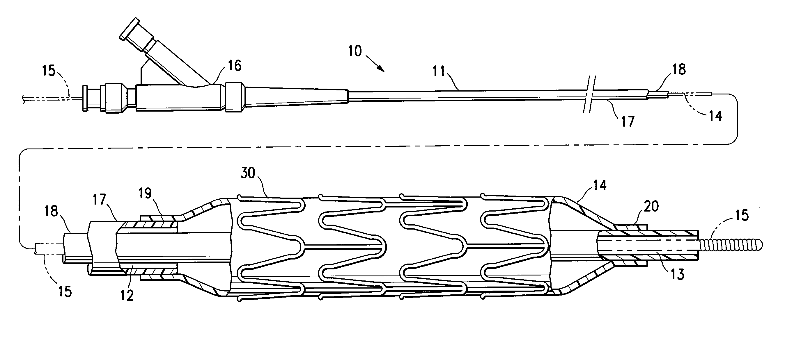
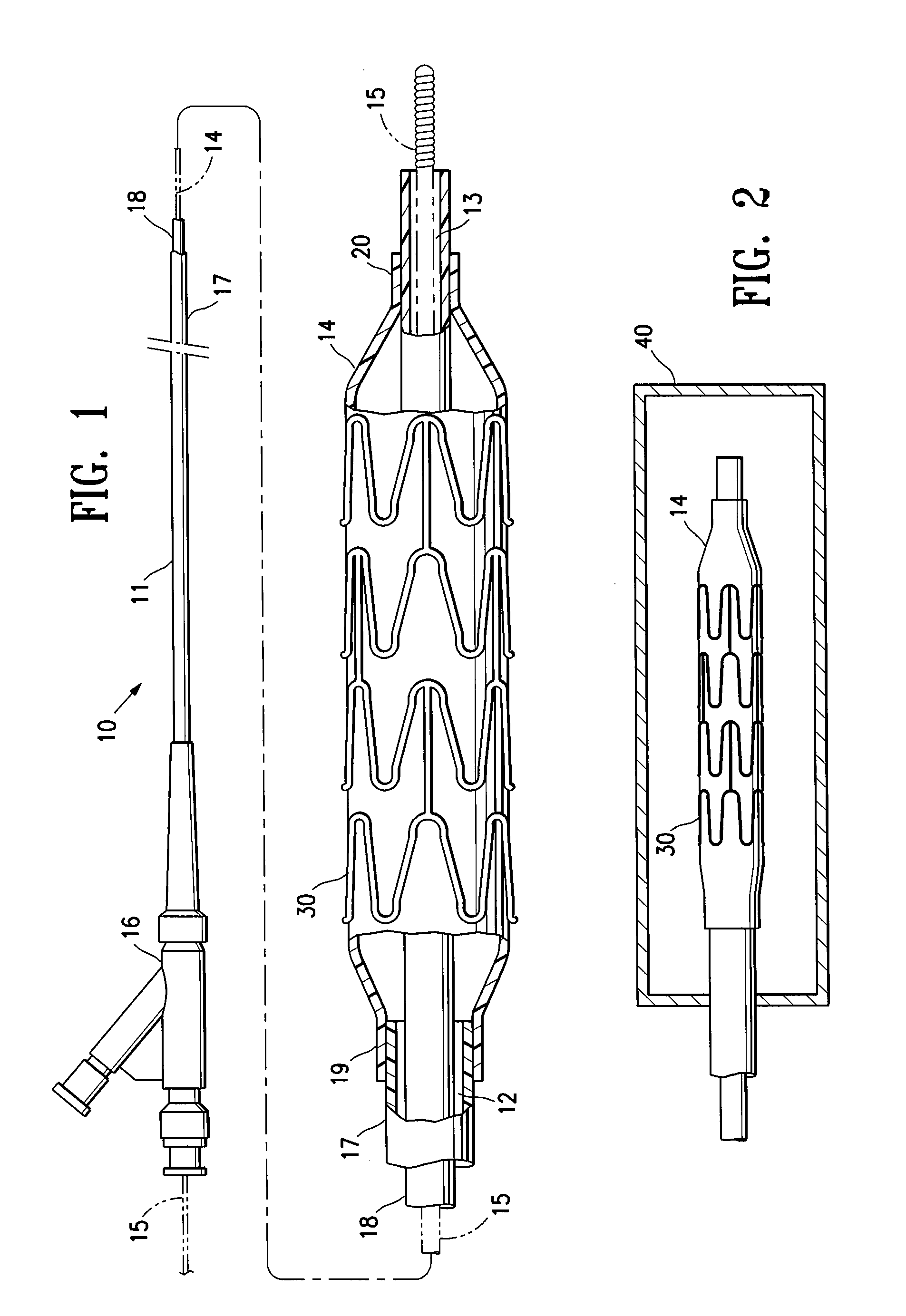
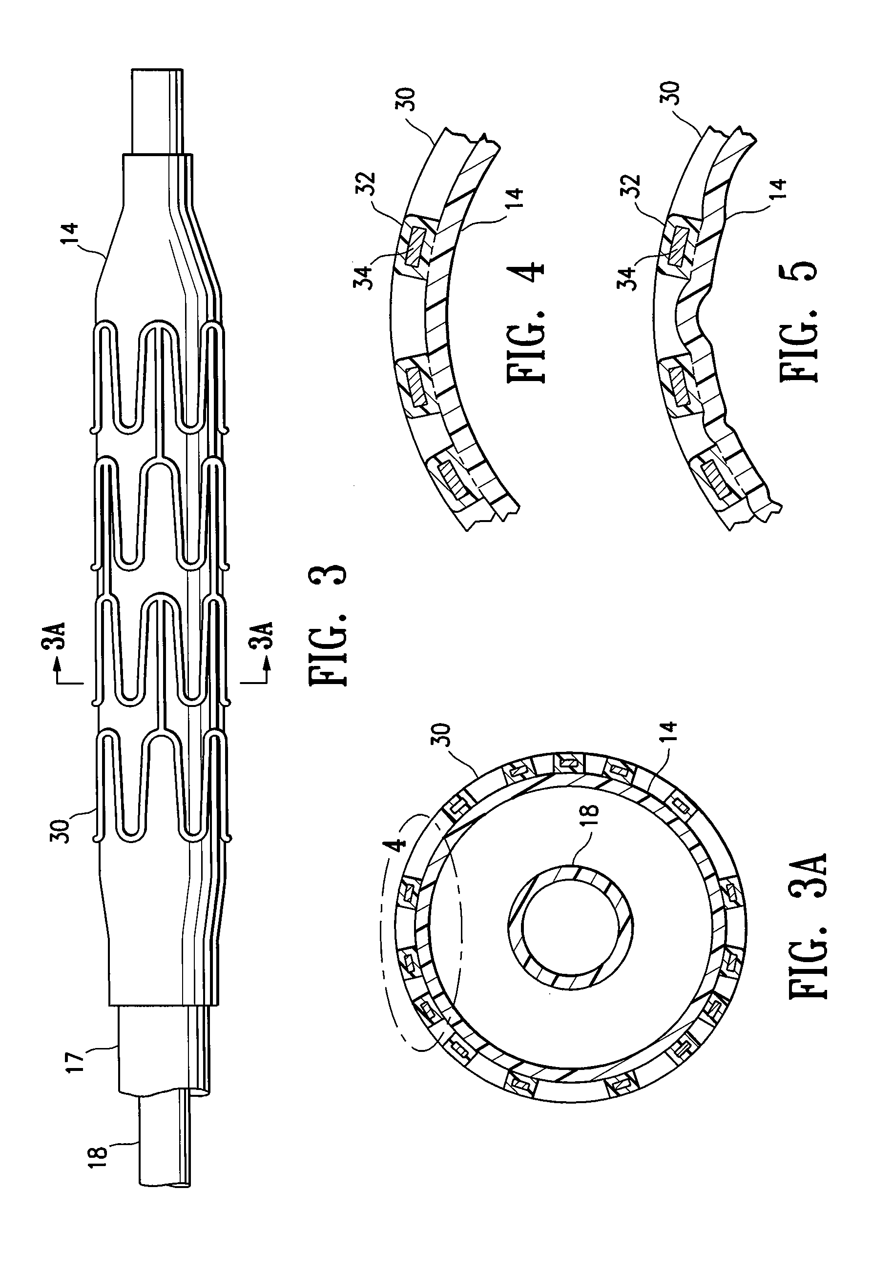
[0005]The invention is directed to a stent delivery catheter system having a catheter with a stent releasably mounted on a stent retention portion of the catheter for delivery and deployment within a patient's body lumen, and a method of mounting the stent on the stent retention portion of the catheter. The method generally includes exposing the stent retention portion and / or the stent to a solvent, the solvent being in the vapor phase. The vapor phase solvent typically softens the stent retention portion of the catheter, and / or, in one embodiment in which the stent has a coating on the stent body, the vapor phase solvent softens the stent coating. Softening the stent retention portion and / or stent coating facilitates releasably mounting the stent on the stent retention portion. Preferably, the softening effect of the vapor allows the balloon to be deformed during mounting of the stent on the balloon under conditions of lower pressure and / or temperature compared to the process without the solvent vapor. The method of the invention provides a stent delivery catheter with improved stent retention during advancement of the stent in the patient's body lumen, preferably without inhibiting stent release after expansion of the stent in the patient's body lumen. In a presently preferred embodiment, the stent polymeric coating has a therapeutic agent, and the method of the invention prevents or inhibits disadvantageously affecting the therapeutic agent coating during mounting of the stent on the catheter.
[0009]Use of the softening effect of the solvent vapor in accordance with the invention preferably results in an interference fit and / or adhesion between the balloon and mounted stent. For example, in one embodiment, forcing the balloon and stent together during mounting of the stent causes portions of the softened balloon to protrude a sufficient amount into the spaces between adjacent struts of the stent to inhibit longitudinal movement of the stent mounted on the balloon. However, in an alternative embodiment, the balloon does not protrude in the mounted stent spaces, so that the stent spaces are free or substantially free of the balloon. Although discussed below primarily in terms of a system having a coated stent, it should be understood that in one embodiment the stent is not coated (e.g., a bare metal stent), and stent retention is enhanced primarily due to the portions of the balloon which are caused to protrude into the stent spaces according to a method of the invention.
[0013]In one embodiment, the stent polymeric coating has a therapeutic agent, such as an antirestenosis agent or an antithrombosis agent. The solvent vapor softens the stent polymeric coating and / or the balloon without disadvantageously affecting the therapeutic agent polymeric coating. For example, the softening effect of the solvent vapor avoids the need for exposing the therapeutic agent coating to relatively high temperatures and pressures to soften and force the balloon and stent together during mounting of the stent on the balloon. In conventional methods of mounting a stent on a catheter balloon, the stent is mounted on the balloon with the balloon at elevated temperature and / or pressure. However, because the balloon and / or stent coating are softened by the solvent vapor in the method of the invention, the method securely mounts the stent onto the balloon while avoiding the use of high temperatures and pressures during stent mounting. Thus, in a method of the invention, the stent is mounted onto the balloon with the balloon and stent at room temperature, or at an elevated temperature lower than the elevated temperatures normally used during conventional stent mounting methods. In one embodiment in which the stent is coated with an anti-restenosis drug, the stent coating is at room temperature, or at an elevated temperature of less than about 70° C. to about 80° C., as the stent is mounted on the balloon. Similarly, in one embodiment, lower pressures are used to pressurize the balloon and radially collapse the stent onto the balloon during stent mounting in a method of the invention. Moreover, if no higher temperature or pressure can be used during stent mounting, better stent retention can be obtained at a given temperature and pressure with the solvent vapor than without the solvent vapor (including the temperatures and pressures normally used in conventional stent mounting methods) due to the softening provided by the solvent vapor.
[0014]Unlike a liquid solvent, the solvent vapor avoids the potential leaching of the therapeutic agent from the polymeric coating. Consequently, the therapeutic agent polymeric coating of the stent has a therapeutic agent concentration which is the same or substantially the same as (i.e., not more than about 0 to about 10% less than) a therapeutic agent concentration of the coated stent prior to mounting on the stent receiving portion. Similarly, in one embodiment, exposing the coating to the vapor phase solvent does not cause the therapeutic agent to migrate in the coating, so that the therapeutic agent polymeric coating of the stent mounted on the balloon has a therapeutic agent distribution which is the same or substantially the same as a therapeutic agent distribution of the coated stent prior to mounting on the balloon. Moreover, the solvent vapor preferably does not change the therapeutic agent or polymer morphology (e.g., crystalline structure) of the therapeutic agent polymeric coating, and thus avoids affecting the therapeutic agent release rate from the polymeric coating, so that the therapeutic agent polymeric coating of the stent has a therapeutic agent release rate which is the same or substantially the same as (i.e., not more than about 0 to about 25% different than) a therapeutic agent release rate of the coated stent prior to mounting on the stent receiving portion. Moreover, unlike a liquid solvent which may over-wet the balloon and / or stent, the solvent vapor facilitates exposing the balloon and / or stent to small amounts of solvent over a short duration, which prevents or inhibits the solvent vapor from weakening bonded regions of the stent delivery catheter (e.g., the bonds between the balloon and the catheter shaft). Additionally, the solvent vapor easily evaporates from the balloon and / or stent, so that residual solvent does not remain behind. Thus, the method of the invention preferably avoid the potential of a liquid solvent to pool within folds and spaces of the stent delivery system. These and other advantages of the invention will become more apparent from the following detailed description and exemplary drawings.


