
Textured implant device

a textured bone graft and implant technology, applied in the field can solve the problems of wear, damage, degeneration, etc., and achieve the effect of increasing the resilience of textured bone grafts or implant devices

Inactive Publication Date: 2013-12-05
OSSAWARE BIOTECH
View PDF6 Cites 79 Cited by
  • Summary
  • Abstract
  • Description
  • Claims
  • Application Information

AI Technical Summary

Benefits of technology

The present invention provides a textured bone graft or implant device with a porous or perforated structure that has a number of openings or cavities formed therein. These openings or cavities are defined by a number of units, which increase the resilience of the device and prevent damage to the user's bone materials. The device allows the bone materials of the user to grow and fill into the openings, providing a flexible and compressible structure that optimizes bone growth and stability. Overall, this invention provides an improved bone graft or implant device for use in spinal and orthopedic procedures.

Problems solved by technology

However, the conventional or typical bone grafts, intervertebral implants, intervertebral spacers, textured bone graft devices or the like comprise a constructed or textured spatial member that includes a solid and stable structure and that may include a great hardness that the bone materials or members of the user may be worn out or damaged or degenerated by the conventional or typical bone grafts, intervertebral implants, intervertebral spacers, textured bone graft devices or the like after use.
In addition, the conventional bone grafts, intervertebral implants, intervertebral spacers, textured bone graft devices or the like comprise a solid structure that the bone materials of the human or user may not be easily grown and filled into the conventional or typical bone grafts, intervertebral implants, intervertebral spacers, textured bone graft devices or the like, such that the conventional or typical bone grafts, intervertebral implants, intervertebral spacers, textured bone graft devices or the like may not be formed integral with the bone materials or members of the user.

Method used


Image

  • Textured implant device
  • Textured implant device
  • Textured implant device

Examples


Embodiment Construction

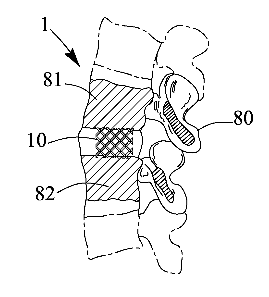
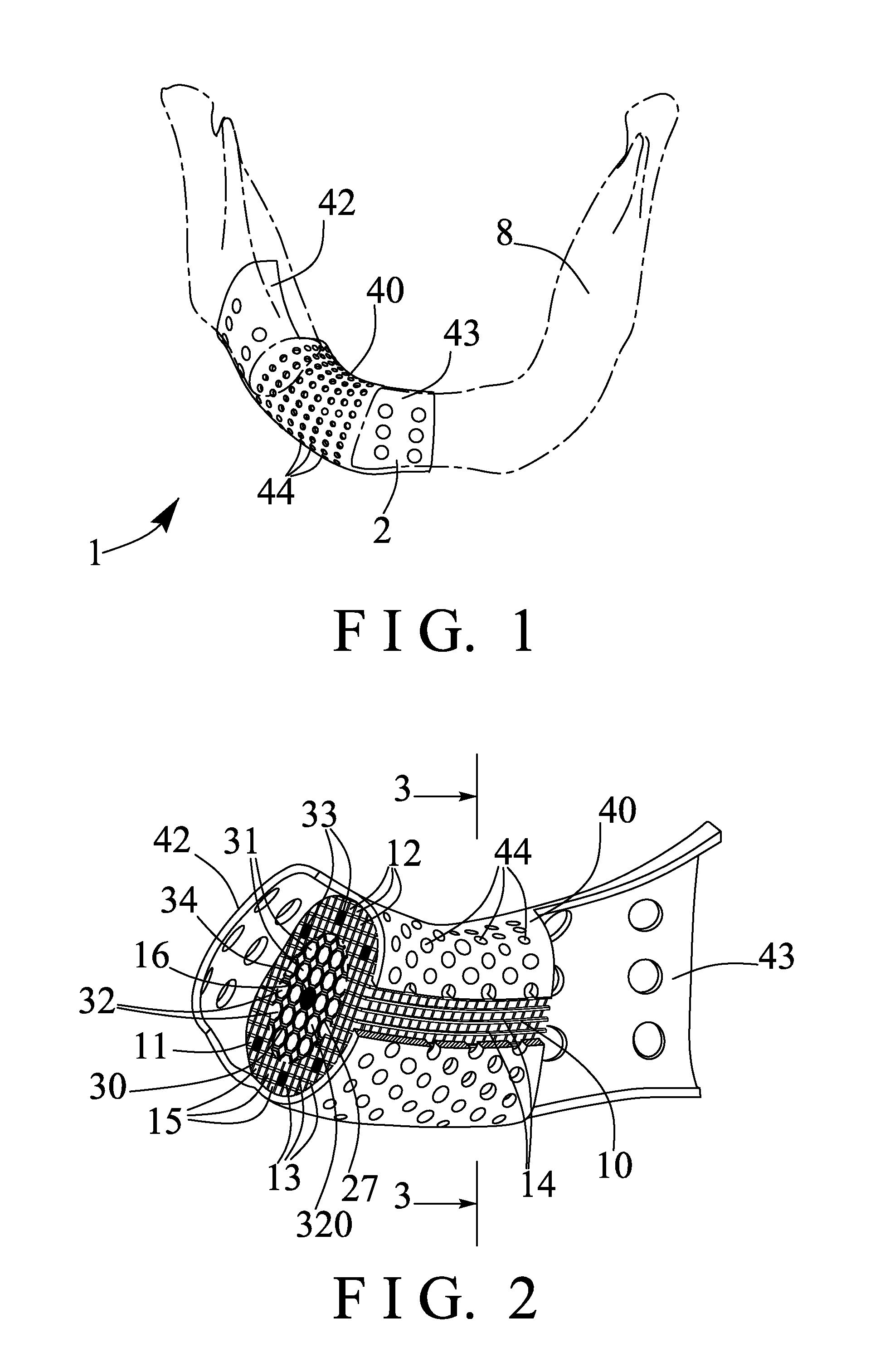
[0040]Referring to the drawings, and initially to FIGS. 1-3, a textured bone graft or implant device 1 in accordance with the present invention is generally provided for being filled or fitted or engaged into the damaged or degenerated bone materials or members 8, 80, such as the mandible 8 (FIG. 1), the spinal column 80 or vertebrae of a human or user (FIG. 7), or the like for repairing bone defects, for example, the textured implant device 1 may be directly engaged into the damaged or degenerated portion of the mandible 8 (FIG. 1), or may be disposed or attached or mounted or secured or engaged into the space between two vertebral bodies 81, 82 (FIG. 7) for forming or acting as the intervertebral disk and for sustain the vertebral bodies 81, 82 in place.

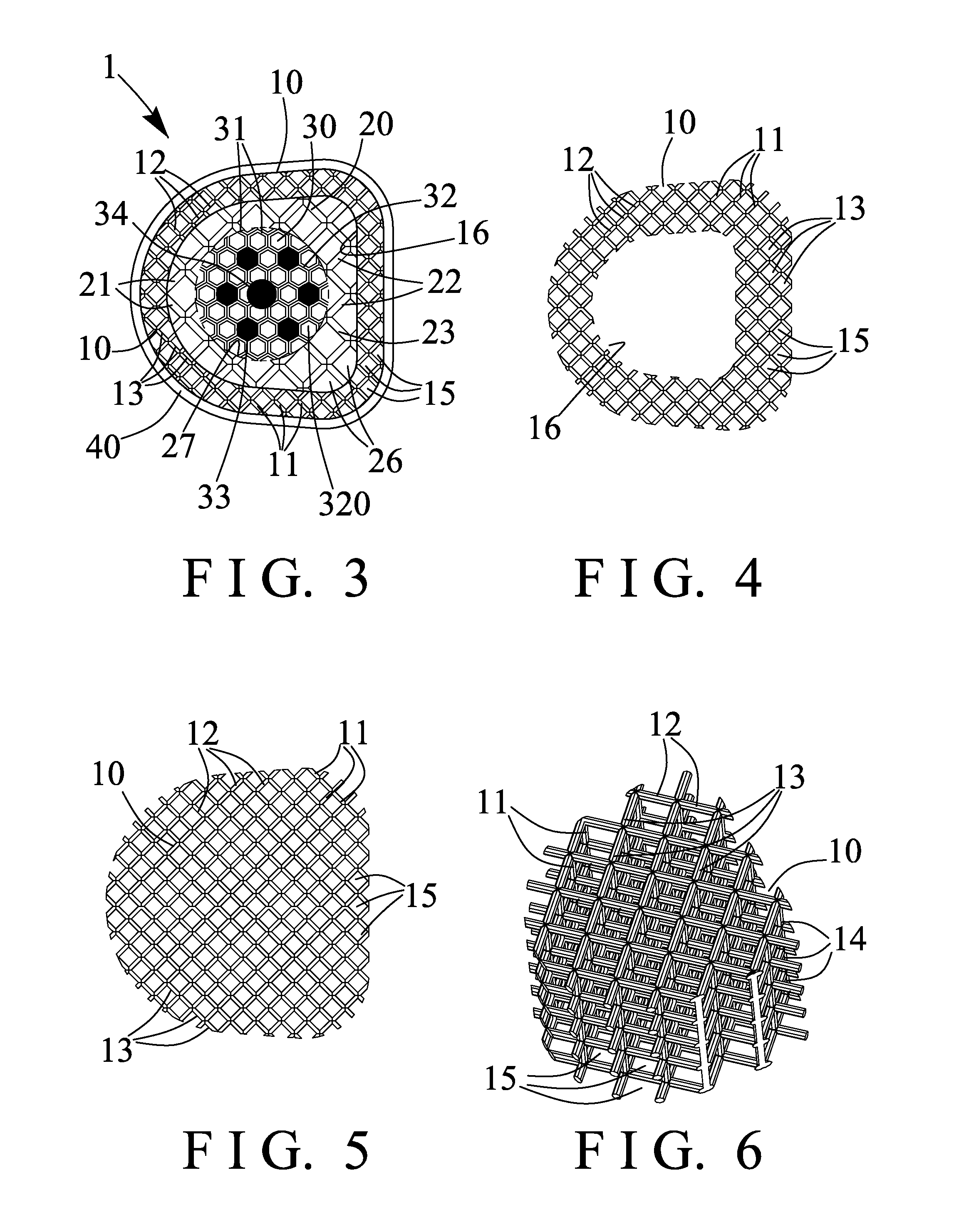
[0041]For example, the textured implant device 1 comprises a constructed or textured three dimensional or spatial body member 10 (FIGS. 3, 4) including a porous or perforated structure formed and defined by a number of cubical or p...


PUM


Abstract

A textured bone graft or implant device includes a spatial member having a number of three dimensional units coupled together, the three dimensional units each include a number of bars coupled together to form a number of openings and to form a porous structure for the spatial member and for allowing the bone materials of the user to be grown and filled into the openings of the textured implant device, the spatial member includes a chamber for engaging with a casing, and the casing includes a compartment for engaging with an inner core, the casing and the inner core each include a number of bars for forming a resilient or flexible or compressible or deformable structure.

Description

BACKGROUND OF THE INVENTION[0001]1. Field of the Invention[0002]The present invention relates to a textured bone graft or implant device, and more particularly to a textured bone graft or implant device including a porous or perforated structure having a number of orifices or cavities or openings formed therein and defined by a number of cubical or parallelepiped or spatial units for increasing the resilience of the textured bone graft or implant device and for preventing the bone materials or members of the user from being damaged by the textured implant device and for allowing the bone materials of the user to be grown and filled into the orifices or cavities or openings of the textured bone graft or implant device.[0003]2. Description of the Prior Art[0004]Typical bone grafts, intervertebral implants, intervertebral spacers, textured bone graft devices or the like have been developed and provided for being filled or fitted or engaged into the bone materials or members of the huma...

Claims


Application Information

Patent Timeline
IPC IPC(8): A61F2/44
CPCA61F2/44A61F2/2803A61F2/2846A61F2/4455A61F2/447A61F2002/30011A61F2002/30112A61F2002/30261A61F2002/3028A61F2002/30303A61F2002/30784A61F2002/30904A61F2002/3092A61B17/864
Inventor HUANG, MENG FENG
Owner OSSAWARE BIOTECH
Learn More