Numerical Simulation Of A Structure Having A Heat-Affected Zone Using A Finite Element Analysis Model

a numerical simulation and analysis model technology, applied in the field of computer aided engineering analysis, can solve the problems of tedious input requirements, difficult to change the model configuration, and weak lines in the vicinity of heat sources for potential structural failur

Inactive Publication Date: 2013-12-05
LIVERMORE SOFTWARE TECH
View PDF3 Cites 10 Cited by
  • Summary
  • Abstract
  • Description
  • Claims
  • Application Information

AI Technical Summary

Benefits of technology

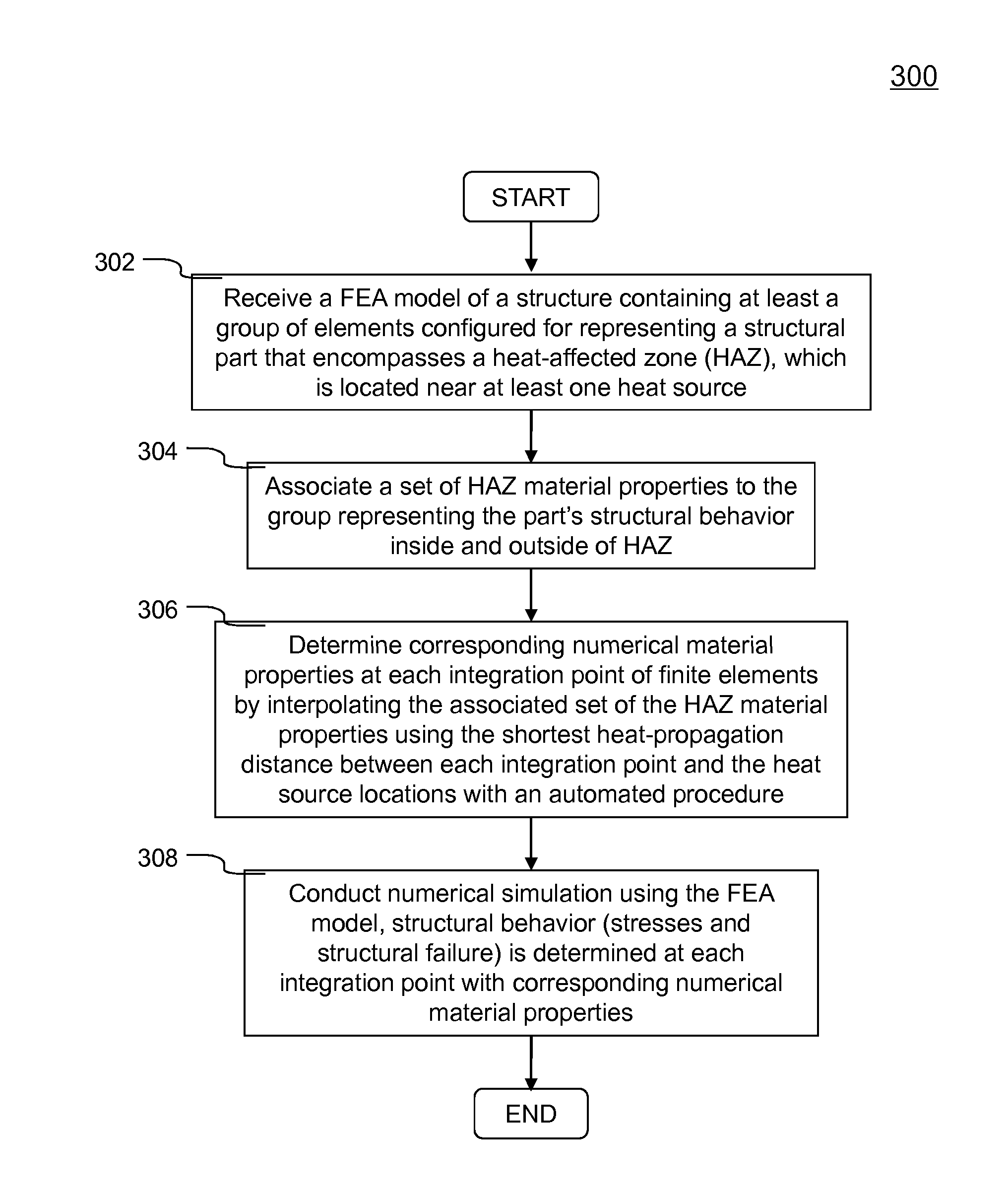
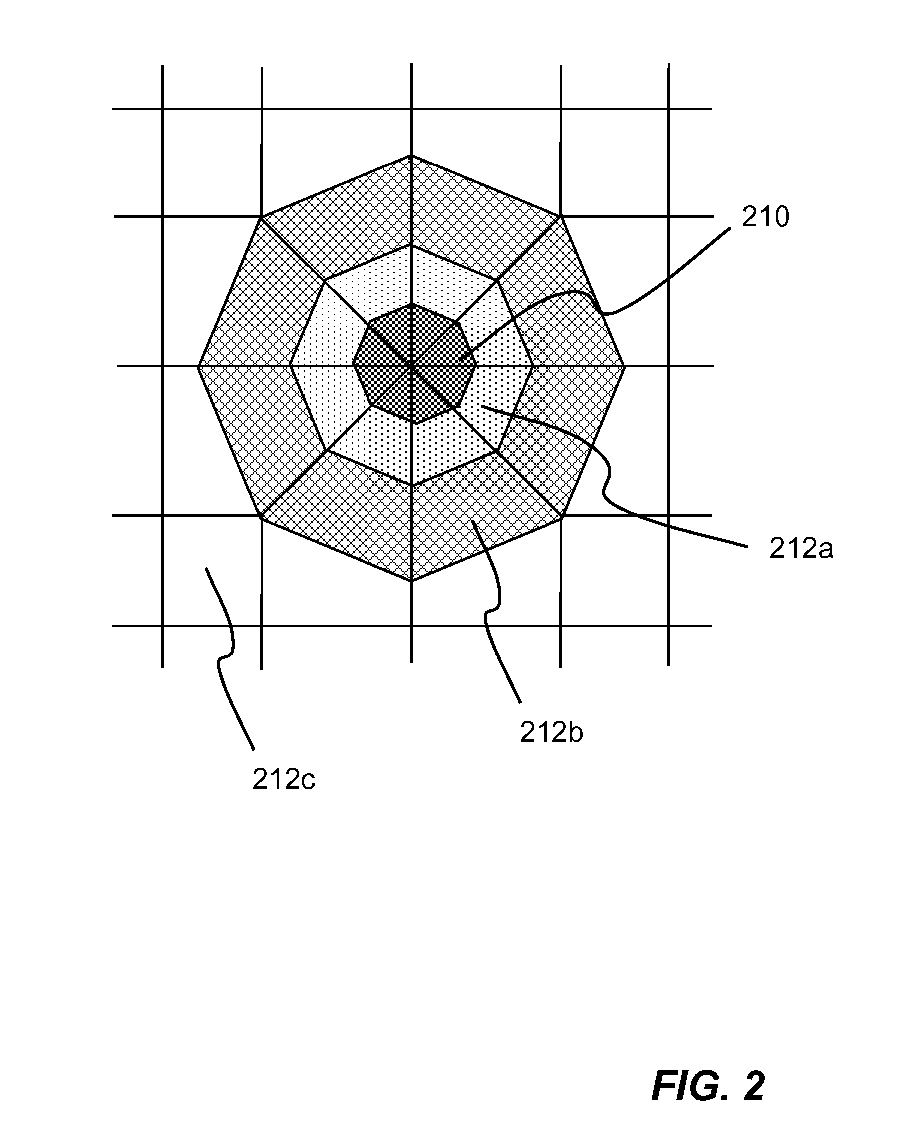
[0011]Methods and systems for conducting numerical simulation of a structure having at least one heat-affected zone using a FEA model are disclosed. According to one exemplary embodiment of the present invention, a FEA model includes at least a group of finite elements representing a welded structural part that encompasses at least one HAZ is defined and received in a computer system having a FEA application module installed thereon. Each finite element in the group is configured with at least one integration point based on FEA. The group of finite elements is associated with a set of HAZ material properties representing structural behavior of the welded structural part inside and outside the HAZ. Corresponding material properties are then determined and assigned to each integration point by interpolating the associated set using the shortest heat-propagation distance between each integration point and the heat source locations (e.g., spotwelds' centroid). A numerical simulation of the structure can then be conducted using the FEA model with corresponding numerical material properties determined at each integration point. According to another aspect of the present invention, the parts in a FEA model that reference the HAZ constitutive model are automatically initiated and no other input is necessary. The present invention eliminates the need for the complex meshing techniques (e.g., the FEA mesh in FIG. 2) presently used in industry.

Problems solved by technology

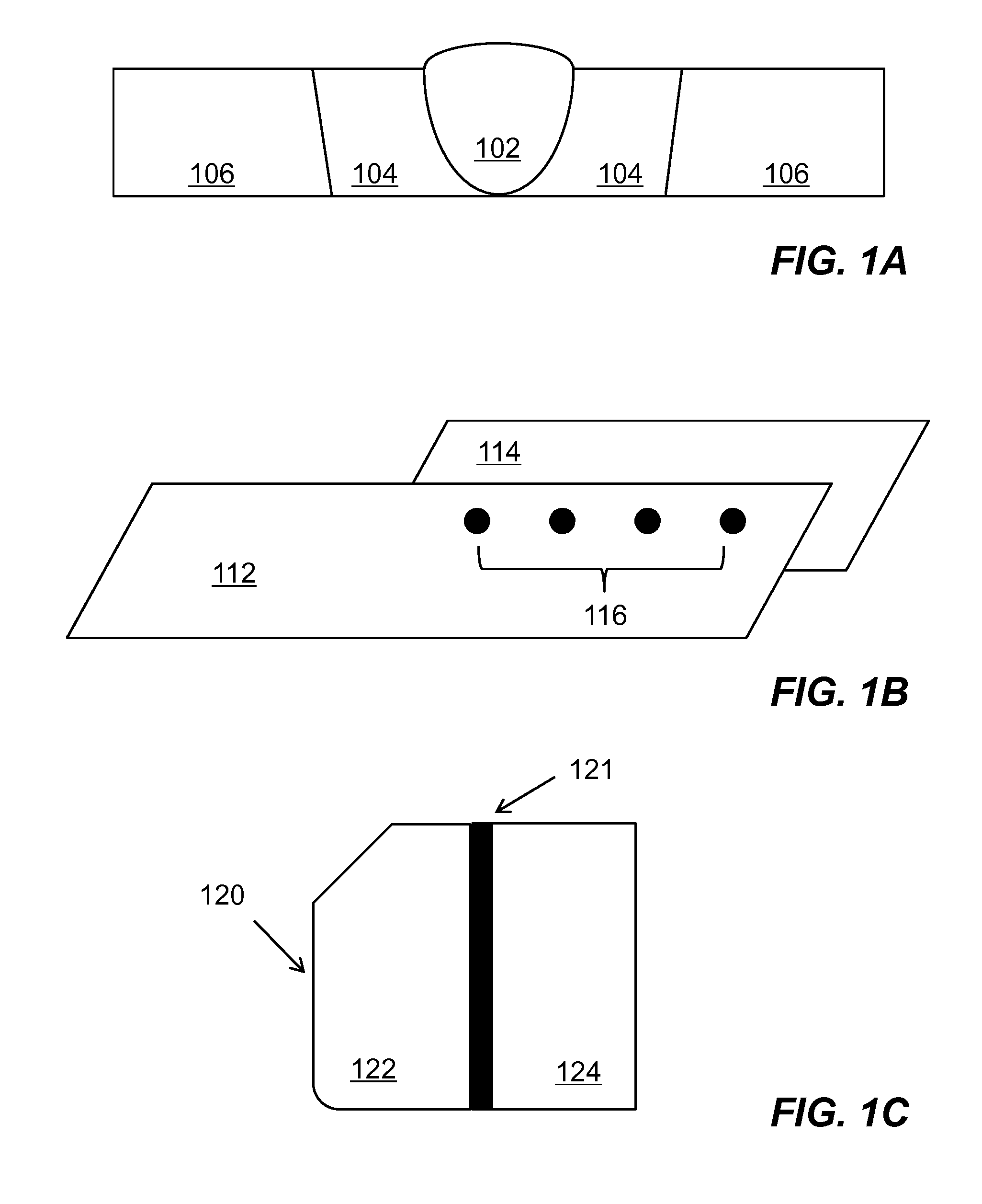
As a result, lines of weakness are created in the vicinity of the heat sources for potential structural failure, particularly under crash loading.
One of the problems with these prior approaches is the tedious input requirements.
It requires the user to define numerous material properties to account for different distances from the heat source, which made it difficult to change the model configuration (e.g., size of the element near the heat source).
Moreover, the task of creating a FEA model is labor intensive since a vehicle contains thousands of spotwelds.

Method used


Image

  • Numerical Simulation Of A Structure Having A Heat-Affected Zone Using A Finite Element Analysis Model
  • Numerical Simulation Of A Structure Having A Heat-Affected Zone Using A Finite Element Analysis Model
  • Numerical Simulation Of A Structure Having A Heat-Affected Zone Using A Finite Element Analysis Model

Examples


Embodiment Construction

[0025]In the following description, numerous specific details are set forth in order to provide a thorough understanding of the present invention. However, it will become obvious to those skilled in the art that the present invention may be practiced without these specific details. The descriptions and representations herein are the common means used by those experienced or skilled in the art to most effectively convey the substance of their work to others skilled in the art. In other instances, well-known methods, procedures, and components have not been described in detail to avoid unnecessarily obscuring aspects of the present invention.

[0026]Reference herein to “one embodiment” or “an embodiment” means that a particular feature, structure, or characteristic described in connection with the embodiment can be included in at least one embodiment of the invention. The appearances of the phrase “in one embodiment” in various places in the specification are not necessarily all referri...


PUM


Abstract

Methods and systems for conducting numerical simulation of a structure having HAZ using a FEA model are disclosed. A FEA model includes at least a group of finite elements representing a welded structural part that encompasses at least one HAZ is defined and received in a computer system. Each finite element in the group is configured with at least one integration point according to FEA. The group of finite elements is associated with a set of HAZ material properties representing structural behavior of the welded structural part inside and outside the HAZ. Corresponding material properties are then determined and assigned to each integration point by interpolating the associated set using the shortest heat-propagation distance between each integration point and the heat source locations (e.g., spotwelds' centroid) with an automated procedure that requires no additional input after the HAZ material properties have been defined.

Description

FIELD OF THE INVENTION[0001]The present invention generally relates to computer aided engineering analysis, more particularly to methods and systems for conducting a numerical simulation of a structure having heat-affected zone, which is located in the vicinity of heat sources (e.g., welding).BACKGROUND OF THE INVENTION[0002]Computer aided engineering (CAE) has been used for supporting engineers in many tasks. For example, in a structure or engineering product design procedure, CAE analysis, particularly finite element analysis (FEA), has often been employed to predict structural behavior (e.g., stresses, displacements, etc.) under various simulated loading conditions (e.g., static or dynamic).[0003]FEA is a computerized method widely used in industry to numerically simulate (i.e., model and solve in a computer system) engineering problems relating to complex products or systems (e.g., cars, airplanes, consumer products, etc.) such as three-dimensional non-linear structural design a...

Claims


Application Information

Patent Timeline
Patent Type & Authority Applications(United States)
IPC IPC(8): G06F17/50
CPCG06F30/23
Inventor HALLQUIST, JOHN O.
Owner LIVERMORE SOFTWARE TECH
Why Eureka
Try Eureka