
Anchor trolley and fall arrest system and method implementing the same

a technology of an anchor trolley and a fall arrest system, which is applied in the direction of safety belts, sports apparatus, building scaffolds, etc., can solve the problems of negating the need for third-party assistance to rescue workers, extreme undesirable effects, and worker orthostatic intolerance or suspension trauma

Active Publication Date: 2013-12-12
PROMISE TO PERFORM IND INC
View PDF23 Cites 22 Cited by
  • Summary
  • Abstract
  • Description
  • Claims
  • Application Information

AI Technical Summary

Benefits of technology

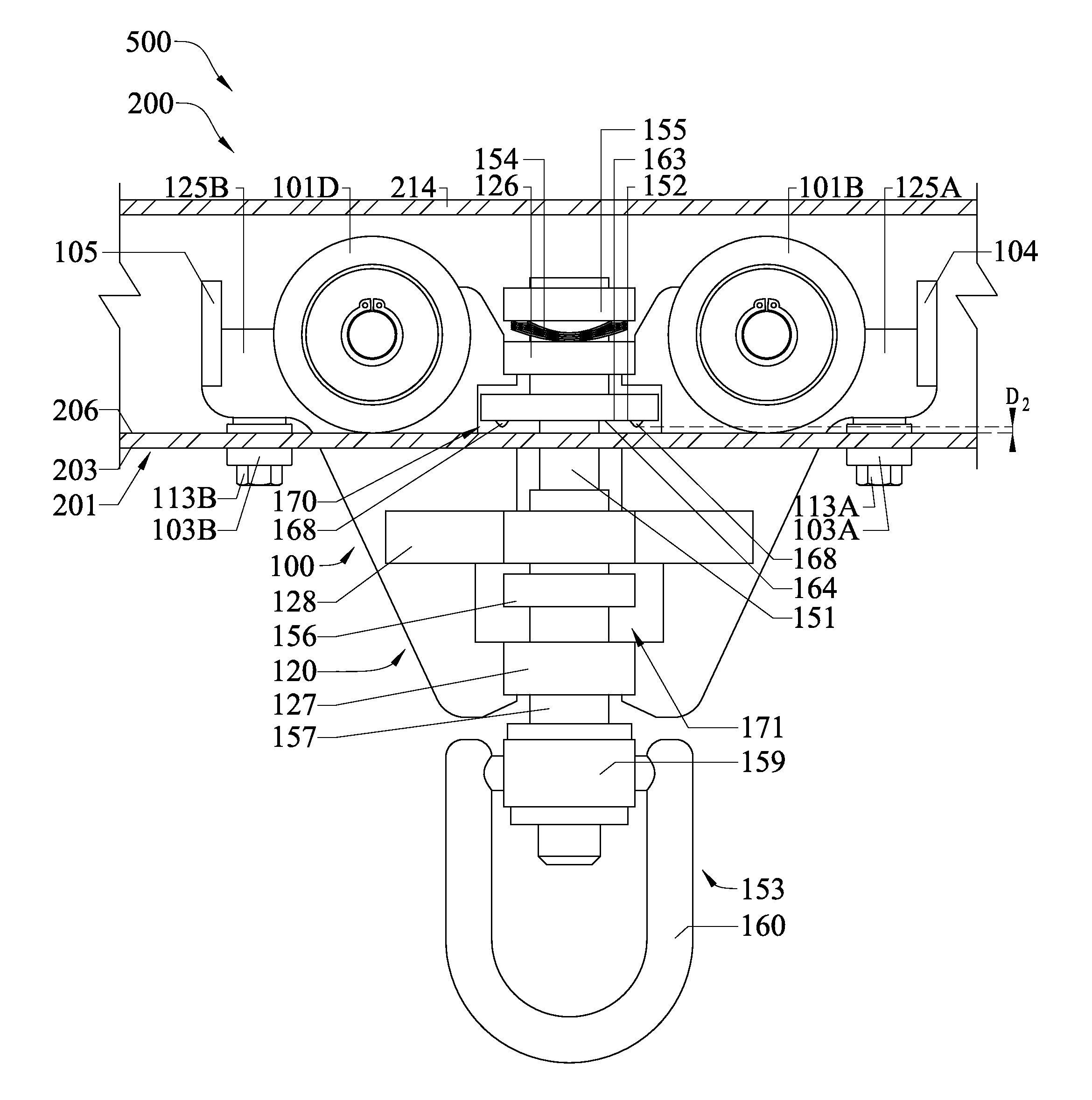
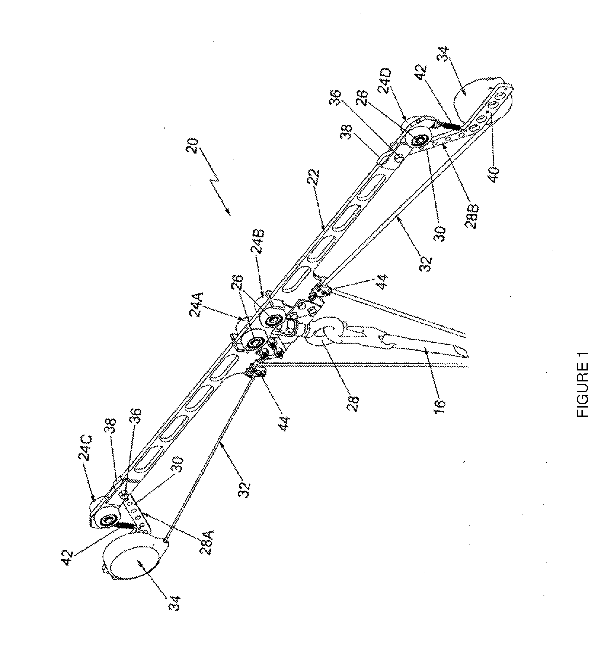
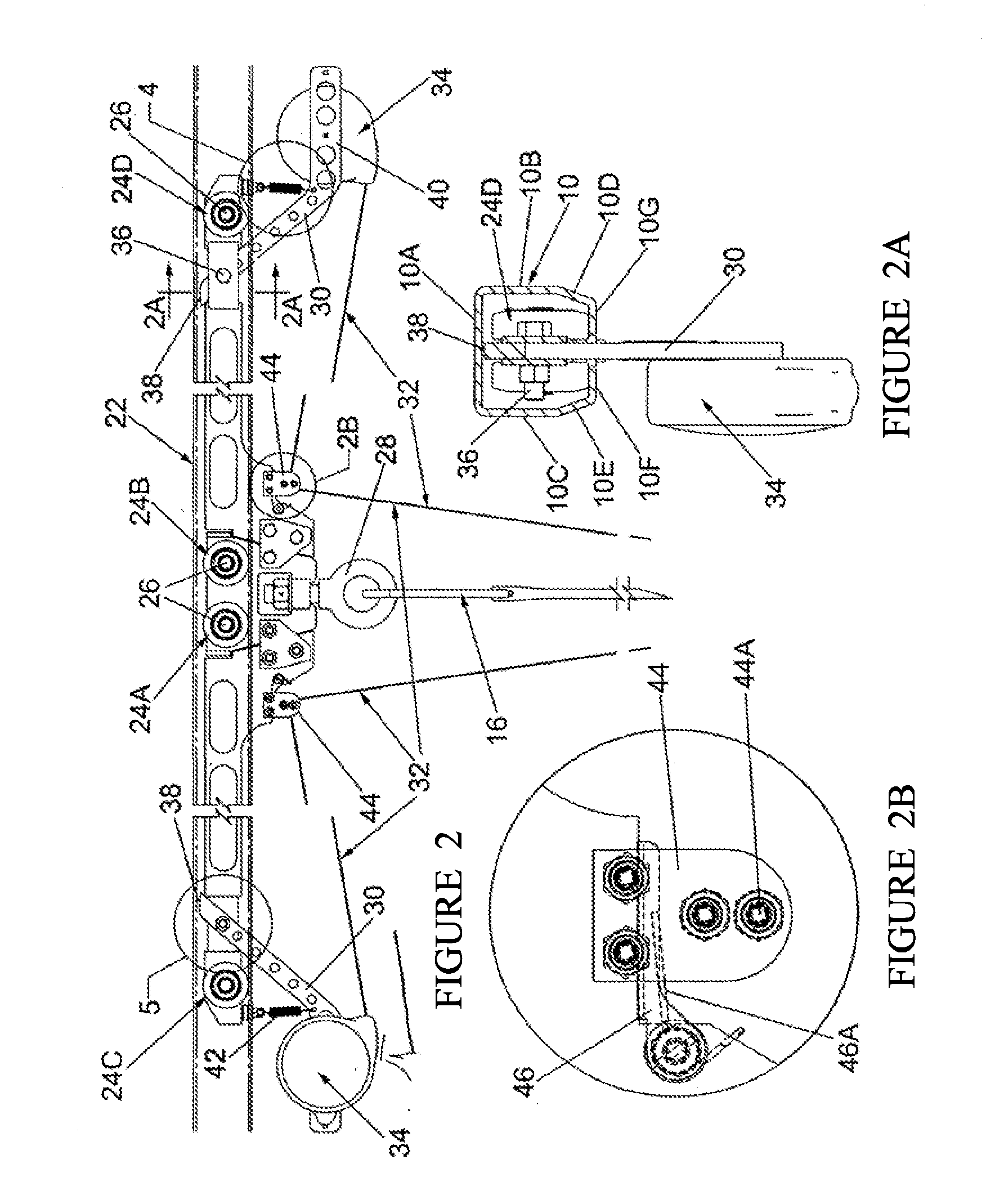
The present invention is a fall arrest apparatus, system, and method that can be used to prevent a person from falling off a work surface or structure. The invention includes a rail and a trolley with a brake sub-system that can be altered between an arrest state and a free state. The brake sub-system includes a brake rod, a brake pad, a lanyard connector, and a resilient element that biases the brake sub-system into the free state. The trolley has wheels in rolling contact with the rail and can move along the rail while the person moves on the work surface. The invention also includes a trolley for movement along an elevated track to support a person who has fallen off a structure adjacent the track. The trolley can be fixed at a fixed longitudinal position on the track and can move along the track as the person swings below it. The technical effects of the invention include providing a reliable and effective means to prevent falls and injuries during construction and maintenance activities.

Problems solved by technology

Many work situations require workers to be positioned on top of platforms or vehicles that cannot be practically protected by a guardrail system enclosing the work surface.
This can be extremely undesirable because if a worker is left hanging for an extended period of time, the worker may suffer from orthostatic intolerance or suspension trauma.
Thus, a need exists for a fall arrest apparatus system and / or method that prevents a worker who falls from a work surface from suffering orthostatic intolerance and negates the need for third party assistance to rescue the worker.

Method used


Image

  • Anchor trolley and fall arrest system and method implementing the same
  • Anchor trolley and fall arrest system and method implementing the same
  • Anchor trolley and fall arrest system and method implementing the same

Examples


Embodiment Construction

[0043]The following description of the preferred embodiment(s) is merely exemplary in nature and is in no way intended to limit the invention, its application, or uses.

[0044]The description of illustrative embodiments according to principles of the present invention is intended to be read in connection with the accompanying drawings, which are to be considered part of the entire written description. In the description of embodiments of the invention disclosed herein, any reference to direction or orientation is merely intended for convenience of description and is not intended in any way to limit the scope of the present invention. Relative terms such as “lower”, “upper,”“horizontal,”“vertical,”“above,”“below,”“up,”“down,”“top” and “bottom” as well as derivatives thereof (e.g., “horizontally”“downwardly,”“upwardly,” etc.) should be construed to refer to the orientation as then described or as shown in the drawing under discussion. These relative terms are for convenience of descript...


PUM


Abstract

A fall arrest anchor trolley for arresting the fall of a user. In one embodiment, the invention can be a fall arrest trolley comprising: a body a brake sub-system, and a plurality of wheels rotatably coupled to the body, wherein bottoms of the plurality of wheels collectively define a rolling plane; the brake sub-system comprising a brake rod, a brake pad connected to the brake rod, a lanyard connector connected to the brake rod, and a resilient element; the brake rod slidably coupled to the body so that the brake sub-system is alterable between: (1) a free state in which the brake pad is spaced a distance above the rolling plane; and (2) an arrest state in which at least a portion of the brake pad is located within the rolling plane; the resilient element biasing the brake sub-system into the free state.

Description

CROSS-REFERENCE TO RELATED APPLICATIONS[0001]The present application is a continuation-in-part of U.S. patent application Ser. No. 12 / 500,897, filed Jul. 10, 2009, the entirety of which is hereby incorporated by reference. The present application also chums the benefit of U.S. Provisional Patent Application No. 61 / 580,940 filed Dec. 28, 2011, the entirety of which is hereby incorporated by reference.FIELD OF THE INVENTION[0002]The present invention relates generally to a fall protection apparatus, and more specifically to a fall protection apparatus that arrests longitudinal movement of as trolley along a rail upon a user falling from a work surface.BACKGROUND OF THE INVENTION[0003]Many work situations require workers to be positioned on top of platforms or vehicles that cannot be practically protected by a guardrail system enclosing the work surface. To prevent the workers from falling from such elevated positions and thereby sustaining serious or fatal injuries, various fall prote...

Claims


Application Information

Patent Timeline
IPC IPC(8): A62B35/00
CPCA62B35/0081A62B35/0062A61H3/008A62B35/0043B61D1/00B65G9/006B66C9/18
Inventor GALPIN, ARNOLD T.PISTTI, DAVID A.
Owner PROMISE TO PERFORM IND INC
Learn More