Method For Measuring Subterranean Formation Density Using A Neutron Generator
a technology of neutron generator and formation density, which is applied in the direction of measurement devices, instruments, nuclear radiation detection, etc., can solve the problems of significant errors in formation density estimation and inaccurate disclosure methods, and achieve the effect of improving accuracy and formation density
- Summary
- Abstract
- Description
- Claims
- Application Information
AI Technical Summary
Benefits of technology
Problems solved by technology
Method used
Image


Examples
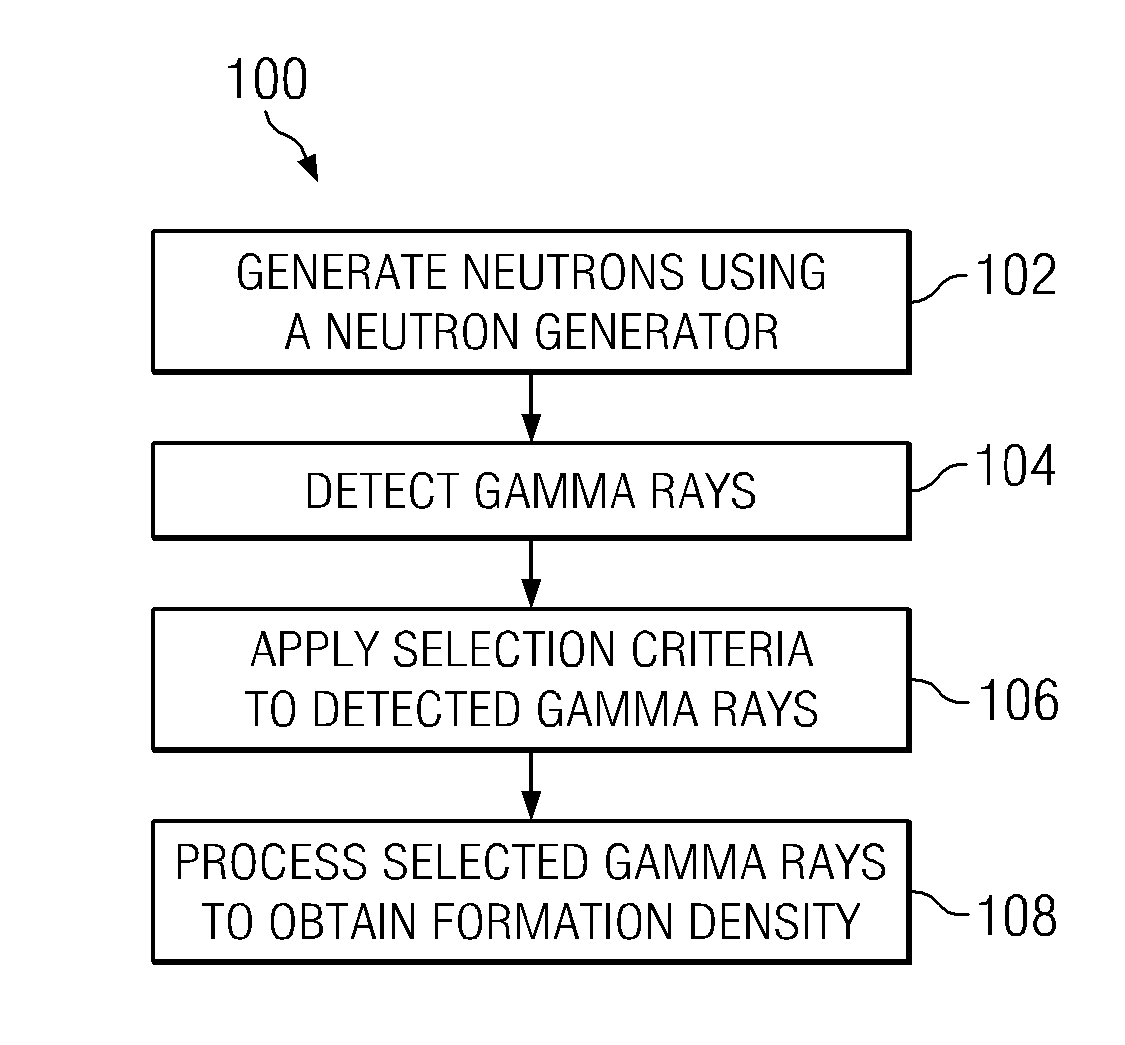
embodiment 100
[0021]FIG. 2 depicts a flow chart of one exemplary method embodiment 100 in accordance with the present invention. Method 100 includes a method for estimating a bulk formation density from the detection of gamma rays. At 102 neutrons are generated using a neutron generator, for example, an accelerator based generator making use of the deuterium-tritium (D-T) fusion reaction. The neutrons emerge from the generator and interact with the borehole (i.e., with the environment surrounding the borehole including the tool, the borehole fluid and the formation) to produce secondary gamma rays as described above in the Background Section. These gamma rays may be detected at 104 using one or more gamma ray detectors deployed on the downhole tool. Predetermined selection criteria are applied to the detected gamma rays at 106. Gamma rays that meet the criteria are selected while that those that do not meet the criteria are rejected. The selected gamma rays are then processed at 108 to compute a ...
embodiment 150
[0026]FIG. 5 depicts a flow chart of an alternative method embodiment 150 in accordance with the present invention. Method 150 is similar to method 100 in that it includes a method for computing a formation density from the detection of gamma rays. Neutrons are generated using a neutron generator and emitted into a subterranean formation at 152. The neutron generator may include, for example, an accelerator based generator making use of a deuterium-tritium (D-T) fusion reaction as described in more detail above with respect to FIGS. 2 and 3. Gamma rays are detected at 154 using at least one gamma ray detector (e.g., detectors 66 on FIG. 3). Alpha particles are detected at 156 using at least one alpha particle deployed in close proximity to the neutron generator (e.g. detector(s) 58 on FIG. 3). Neutrons may also optionally be detected at 156 (e.g., using neutron detector 64 on FIG. 3).
[0027]The detected alpha particles and gamma rays are evaluated in combination at 160 to determine w...
PUM
 Abstract
Description
Claims
Application Information