Near infrared illuminator

illuminator technology, applied in the field of near infrared illuminator, can solve the problems of inability to develop an optical axis adjusting device dedicated to near infrared rays, inability to adjust the optical axis of such a near infrared illuminator with a common headlight tester, and high cos

Inactive Publication Date: 2013-12-12
STANLEY ELECTRIC CO LTD
View PDF12 Cites 14 Cited by
  • Summary
  • Abstract
  • Description
  • Claims
  • Application Information

AI Technical Summary

Problems solved by technology

When the system adopts a far infrared camera, the cost thereof can be expensive.
Therefore, an optical axis of such a near infrared illuminator cannot be adjusted with a common headlight tester (see, for example, Japanese Patent Application Laid-Open No. 2001-13039), which is conventionally used for optical axis adjustment.
Further, to develop an optical axis adjusting device dedicated for ...

Method used


Image

  • Near infrared illuminator
  • Near infrared illuminator
  • Near infrared illuminator

Examples


Embodiment Construction

[0025]A description will now be made below to near infrared illuminators of the presently disclosed subject matter with reference to the accompanying drawings in accordance with exemplary embodiments.

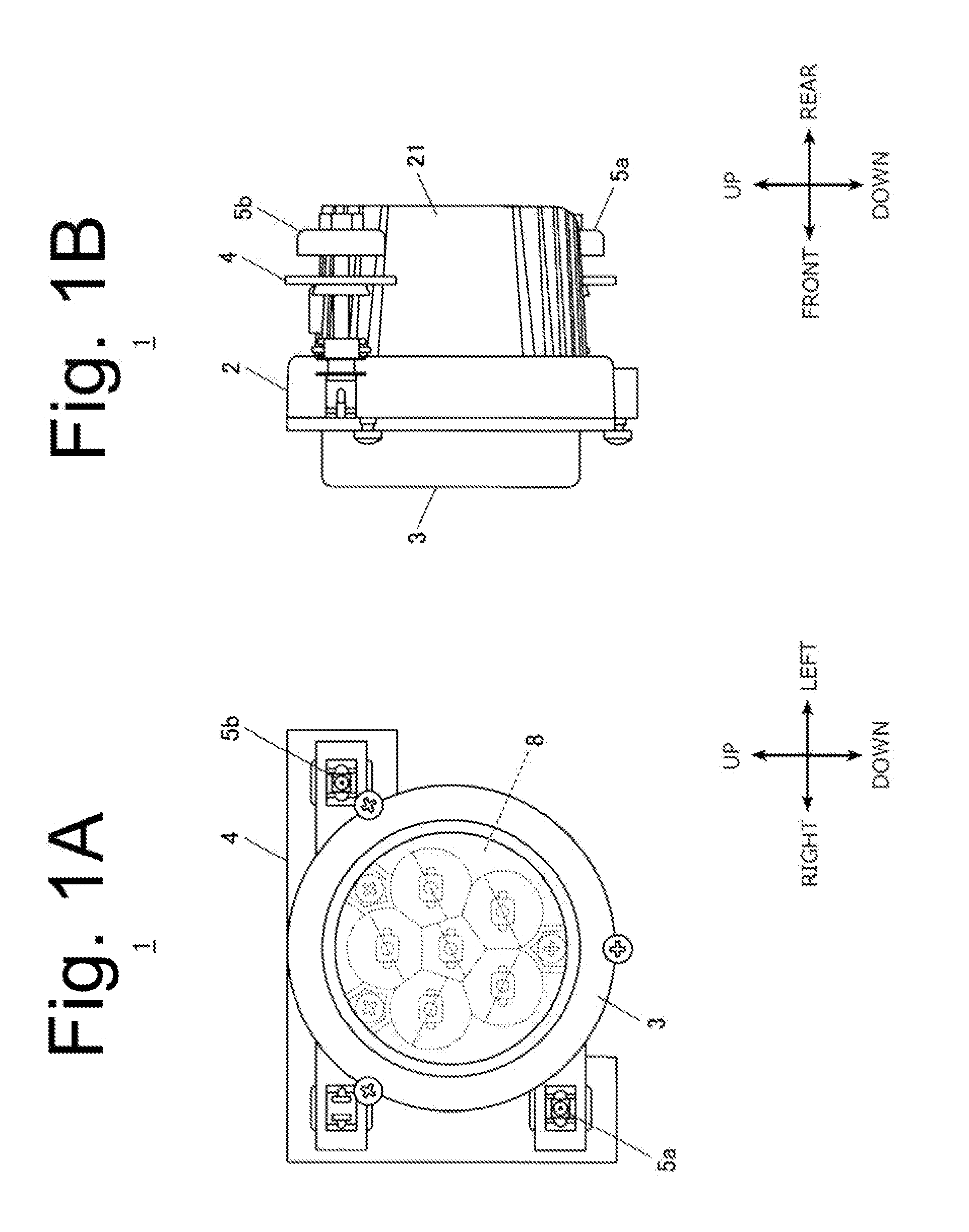
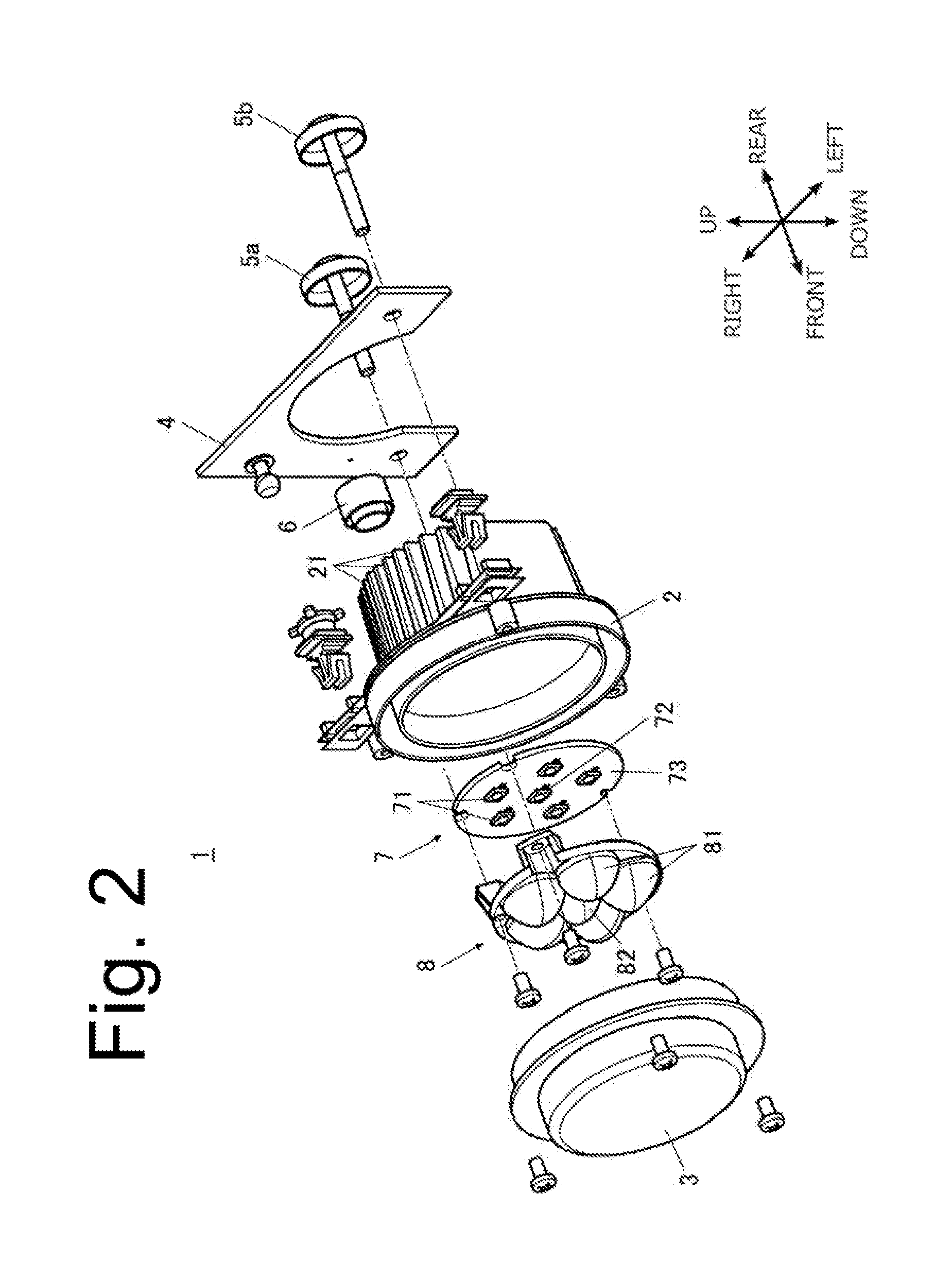
[0026]FIGS. 1A and 1B are a front view illustrating a near infrared illuminator made in accordance with principles of the presently disclosed subject matter, and a right side view thereof, respectively. FIG. 2 is a perspective exploded view illustrating the near infrared illuminator of FIG. 1.

[0027]Note that in the present description, the directions of “front (forward),”“back (rear, rearward),”“left,”“right,”“up (high),” and “down (low)” mean the directions when viewed with respect to the near infrared illuminator 1 installed in a vehicle body of an automobile to project light forward of the vehicle body.

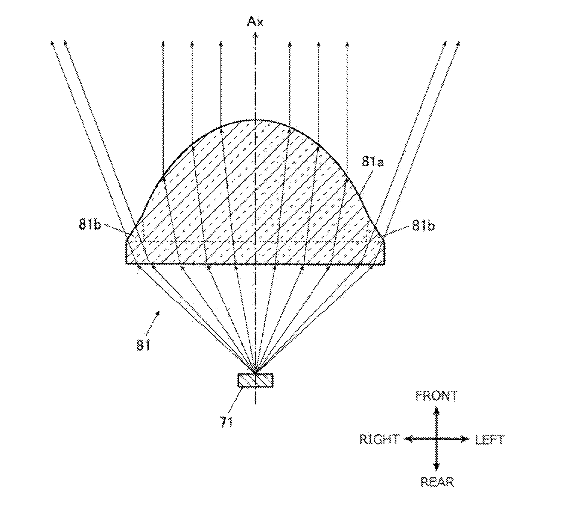
[0028]The near infrared illuminator 1 can be utilized in a night vision system installed in a vehicle body, so as to project near infrared light forward to form a predetermined light d...


PUM


Abstract

A near infrared illuminator can facilitate the adjustment of an optical axis thereof with favorable accuracy. The near infrared illuminator can include: a light source configured to emit near infrared rays; and a projector lens configured to project the near infrared rays emitted from the light source forward to form a predetermined light distribution pattern in front thereof. The projector lens can include a light distribution control section configured to project part of the near infrared rays emitted from the light source forward to form the predetermined light distribution pattern, and a marker forming section configured to project part of the near infrared rays emitted from the light source forward to form an alignment marker for positioning the light distribution pattern at a predetermined position beside the light distribution pattern.

Description

[0001]This application claims the priority benefit under 35 U.S.C. §119 of Japanese Patent Application No. 2012-132437 filed on Jun. 12, 2012, which is hereby incorporated in its entirety by reference.TECHNICAL FIELD[0002]The presently disclosed subject matter relates to a near infrared illuminator.BACKGROUND ART[0003]In recent years, various driving support systems such as night vision systems and a marking light have been developed and put to practical use. In general types of driving support systems, an infrared camera can be provided to detect surroundings while illuminating the surroundings with infrared rays. When the system adopts a far infrared camera, the cost thereof can be expensive. In contrast to this, when a system adopts a near infrared camera utilizing near infrared rays for illumination, the system cost can be appropriately lowered.[0004]In such a driving support system utilizing a near infrared camera and a near infrared illuminator, the optical axis of such a near...

Claims


Application Information

Patent Timeline
IPC IPC(8): F21V5/04
CPCF21V5/04B60Q1/0683B60Q1/18F21S41/13F21S41/143F21S41/153F21S41/18F21S41/265G02B3/0056H01L33/58G02B19/00
Inventor OTSUKA, HIDEO
Owner STANLEY ELECTRIC CO LTD
Why Eureka
Try Eureka