Overlock sewing machine

a sewing machine and overlock technology, applied in the field of overlock sewing machines, can solve the problems of increasing the installation space and the number of components, and achieve the effect of strengthening the engagemen

Active Publication Date: 2013-12-19
JUKI CORP
View PDF9 Cites 12 Cited by
  • Summary
  • Abstract
  • Description
  • Claims
  • Application Information

AI Technical Summary

Benefits of technology

[0016]According to the third aspect of the invention, because the biasing means for providing biasing force in the direction in which the notch and the engaging portion firmly adhere to one another is provided for the rod, it is ...

Problems solved by technology

Therefore, there has been a problem that the number of components and the installation space are increased.
Further, because a delinking mechanism is present at a position separated from the rod 4 coupled to the sewing machine main...

Method used


Image

  • Overlock sewing machine
  • Overlock sewing machine
  • Overlock sewing machine

Examples


Embodiment Construction

[0028]Hereinafter, an embodiment of the present invention will be described in detail with reference to the drawings.

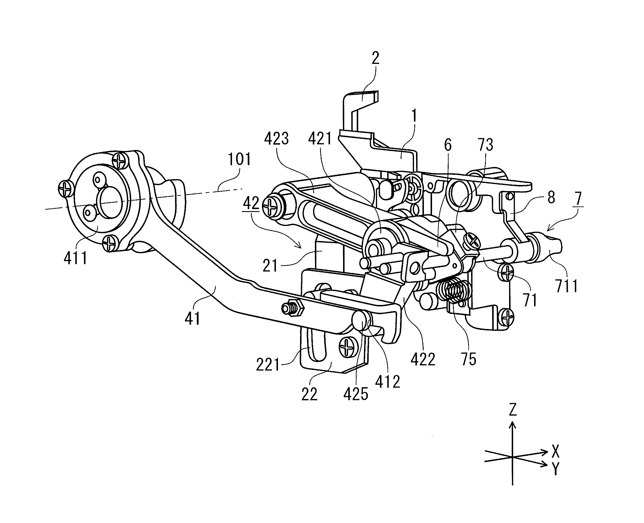
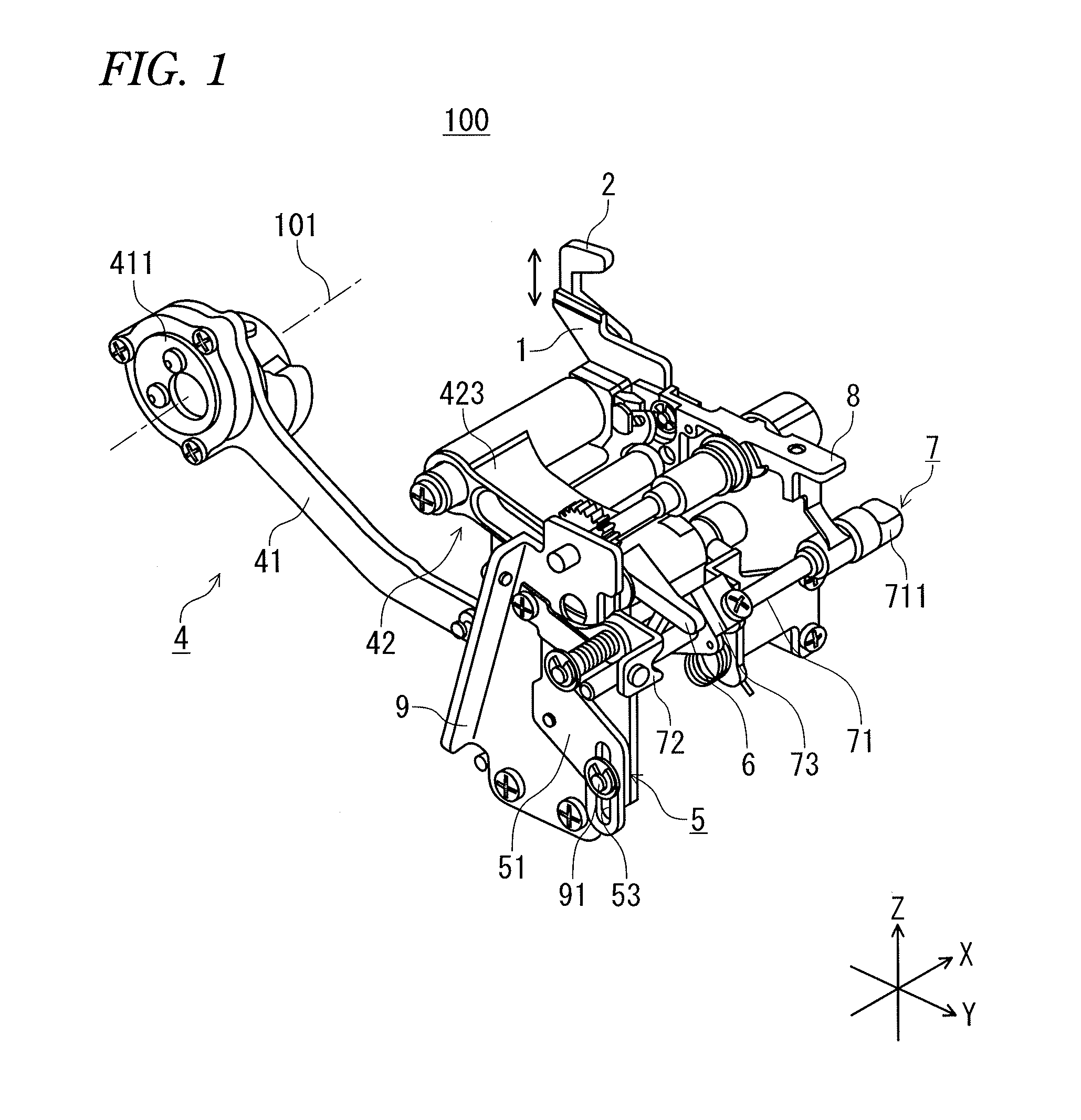
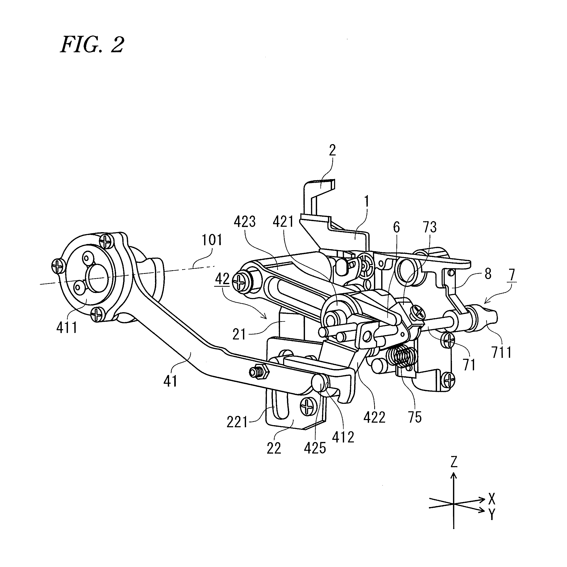
[0029]FIGS. 1 to 3 are perspective views of a configuration of main portions of an overlock sewing machine (hereinafter called a sewing machine) according to the present embodiment, which are respectively viewed from different directions. Further, FIG. 4 is a front view showing the configuration of the main portions of the sewing machine, FIG. 5 is a diagram of one side thereof, and FIG. 6 is a diagram of the other side thereof.

[0030]In addition, a direction parallel to a sewing machine main shaft 101 is defined as an X direction, a direction perpendicular to the X direction on a horizontal plane is defined as a Y direction, and a direction perpendicular to the X direction on a vertical plane is defined as a Z direction.

[0031]As shown in FIGS. 1 to 6, a sewing machine 100 includes a lower knife 1, and an upper knife 2 which is movable to a withdrawn position lower tha...


PUM


Abstract

An overlock sewing machine includes an upper knife which is movable to a withdrawn position or a driving position, an upper knife driving unit which moves the upper knife, an interlocking switching unit which switches between an interlocking state in which the upper knife driving unit and the upper knife are interlock and a release state in which the upper knife driving unit and the upper knife are released, an upper knife position switching unit which switches the upper knife to the driving position or the withdrawn position, and an operating unit which drives the interlocking switching unit and the upper knife position switching unit such that the interlocking switching unit is brought into the interlocking state when the upper knife is switched to the driving position, and the interlocking switching unit is brought into the release state when the upper knife is switched to the withdrawn position.

Description

CROSS-REFERENCE TO RELATED APPLICATIONS[0001]This application is based upon and claims the benefit of priority from Japanese Patent Application No. 2012-133427, filed on Jun. 13, 2012; the entire contents of which are incorporated herein by reference.BACKGROUND OF INVENTION[0002]1. Field of the Invention[0003]The present invention relates to an overlock sewing machine, and in particular, to an overlock sewing machine having an upper knife which cuts a cloth end edge onto which over-edge darning is performed.[0004]2. Related Art[0005]For example, in an overlock sewing machine, an over-edge chain stitching is applied onto the cloth end edge while cutting a cloth end edge by an upper knife which moves up and down so as to interlock with a sewing machine main shaft.[0006]Then, in a case where this upper knife is not used, an overlock sewing machine in which the upper knife is withdrawn from a cloth edge cutting position by stopping the upper knife on the lower side of the throat plate, ...

Claims


Application Information

Patent Timeline
IPC IPC(8): D05B37/06D05B1/12D05B73/12
CPCD05B37/06D05B73/12D05B1/12
Inventor SUGAWARA, KUNIHIKO
Owner JUKI CORP
Why Eureka
Try Eureka