Container Wall for a Container Covered by a Film

a technology for containers and walls, applied in the field of containers, can solve the problems of film slipping out of the rail, increased effort when opening the cover, and the cover may lose its function, and achieve the effect of producing and assembling even more simply

Inactive Publication Date: 2013-12-19
MT ENERGIE GMBH
View PDF7 Cites 1 Cited by
  • Summary
  • Abstract
  • Description
  • Claims
  • Application Information

AI Technical Summary

Benefits of technology

[0010]The object of the invention is to provide a container wall for a container having a device for securing a film made of plastic sealing the container on the upper face in a roof-shaped manner, which can be produced and assembled even more simply.

Problems solved by technology

Thus, as a result of the deformation of the clamping profile or the lack of clamping force in the clamping tube, there is the risk that the film slips out of the rail.
A disadvantage is the increased effort when opening the cover, for example for maintenance purposes.
Moreover, the cover may lose its function when the film is torn, which has to be avoided.
Two undercuts are formed by the projections, which are relatively costly to produce irrespective of whether a separate clamping profile is used or the clamping channel is moulded into the material of the container wall.
Additionally, by means of the two projections, the introduction of the insertion profile into the clamping channel is made more difficult and / or only permitted by specific shaping of the clamping channel.

Method used


Image

  • Container Wall for a Container Covered by a Film
  • Container Wall for a Container Covered by a Film
  • Container Wall for a Container Covered by a Film

Examples


Embodiment Construction

[0044]While this invention may be embodied in many different forms, there are described in detail herein a specific preferred embodiment of the invention. This description is an exemplification of the principles of the invention and is not intended to limit the invention to the particular embodiment illustrated.

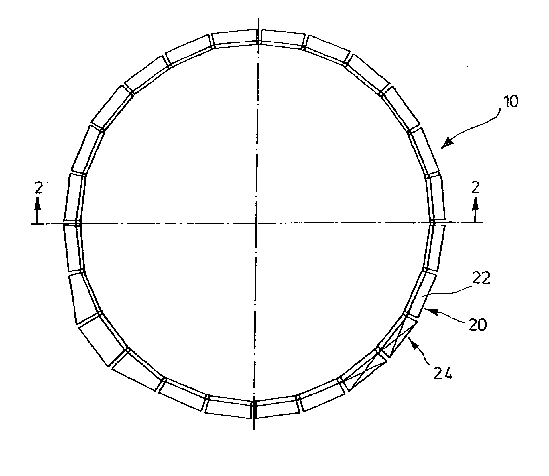
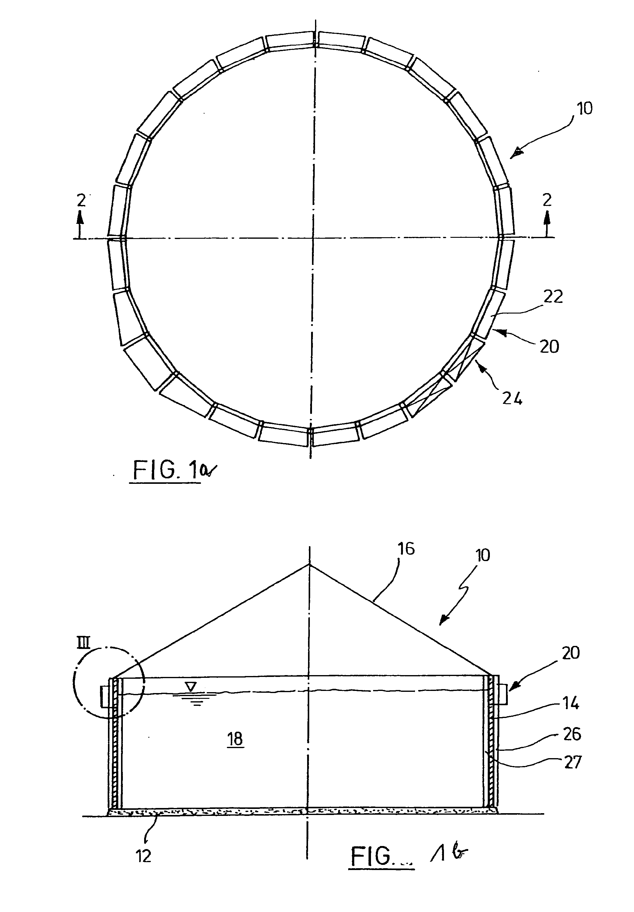
[0045]A container 10 is indicated in FIGS. 1a and b, said container comprising a base 12 made of concrete and a cylindrical wall 14, also made of concrete. The concrete wall is produced, for example, by means of a plurality of shuttering elements arranged externally and internally. At least one plastic film 16 is stretched over the top of the container 10, the edge thereof being secured in the upper region to the outer face of the wall 14, as will be described in more detail below. For example a fermenting agent 18 is located in the container. A peripheral walkway 20 with a handrail is shown on the outer face of the wall 14. The walkway consists of individual walkway elements...


PUM


Abstract

Container wall preferably made of concrete, in particular for containers for the storage and the fermentation of fermenting agents, which in the vicinity of the upper edge has an outwardly open clamping channel with an undercut for clampingly receiving an edge of at least one film made of plastics material covering the container on the upper face, the clamping channel having a narrow, outwardly open entry slot, the height thereof being smaller than the height of an elongate insertion profile insertable into the clamping channel, around which the film may be wound, the cross-sectional dimensions of the clamping channel, the entry slot and the insertion profile being such that the insertion profile in position relative to the entry slot is insertable via said entry slot into the clamping channel and is retained against being moved out of the clamping channel when the film wound around the insertion profile is under tension, characterised in that the narrow entry slot is only defined by an upper projection, whilst the approximately planar lower wall of the clamping channel merges without projections with the entry slot.

Description

CROSS-REFERENCE TO RELATED APPLICATIONS[0001]This is a national stage application of PCT / EP2011 / 006375, Filed on Dec. 16, 2011, which claims priority to DE 10 2010 055 527, filed on Dec. 22, 2010, the entire content of which are hereby incorporated by reference.STATEMENT REGARDING FEDERALLY SPONSORED RESEARCH[0002]Not applicable.BACKGROUND OF THE INVENTION[0003]The invention relates to a container wall according to claim 1.[0004]Containers for the storage and the fermentation of fermenting agents, for example in so-called biogas plants, have sizeable dimensions. Generally they are configured in the manner of a silo and, accordingly, generally have a circular base. The wall is cast, for example, from concrete and the seal at the top is often implemented by means of a roof-shaped film which is retained in a tensioned and raised state by the production of gas or by the introduction of compressed air. In order to secure the film on the edge in an effective manner to the container wall, ...

Claims


Application Information

Patent Timeline
Patent Type & Authority Applications(United States)
IPC IPC(8): B65D90/02
CPCB65D90/02C12M21/04C12M23/26C12M23/36C12M23/46B65D90/06B65D90/08C12M1/107
Inventor BEHRENS, JAN C.F.
Owner MT ENERGIE GMBH
Why Eureka
Try Eureka