Contactless power transmitting device, contactless power receiving device, and contactless power transfer system

a technology of contactless power and transmission device, which is applied in the direction of hybrid vehicles, propulsion by capacitors, battery/cells, etc., can solve the problems of deteriorating transmission efficiency, inability to efficiently and inability to transmit or receive electric power at all, so as to achieve high power transmission efficiency

Active Publication Date: 2013-12-19
TOYOTA JIDOSHA KK +1
View PDF4 Cites 45 Cited by
  • Summary
  • Abstract
  • Description
  • Claims
  • Application Information

AI Technical Summary

Benefits of technology

[0010]The invention provides a contactless power transmitting device, a contactless power receiving device and a contactless power transfer system that are able to align the position of a power transmitting unit with the position of a power receiving unit in a high power transmission efficiency state.

Problems solved by technology

When the magnetic flux distributions of a pair of power transmitting portion and power receiving portion are different from each other, it is not possible to efficiently transmit or receive electric power.
It is inconvenient that electric power cannot be transmitted or received at all because of a mismatch between the magnetic flux distribution of the power transmitting portion and the magnetic flux distribution of the power receiving portion.
Therefore, when a power receiving device is guided to the same position irrespective of a coil type, it may lead to a case where the transfer efficiency deteriorates.

Method used


Image

  • Contactless power transmitting device, contactless power receiving device, and contactless power transfer system
  • Contactless power transmitting device, contactless power receiving device, and contactless power transfer system
  • Contactless power transmitting device, contactless power receiving device, and contactless power transfer system

Examples


first embodiment

[0149]FIG. 15 is a view for illustrating the operation of a contactless power transfer system according to a first embodiment.

[0150]As shown in FIG. 15, a vehicle 100A is a vehicle in which the circular-type power receiving coil 111A is installed. A vehicle 100B is a vehicle in which the polarized-type power receiving coil 111B is installed.

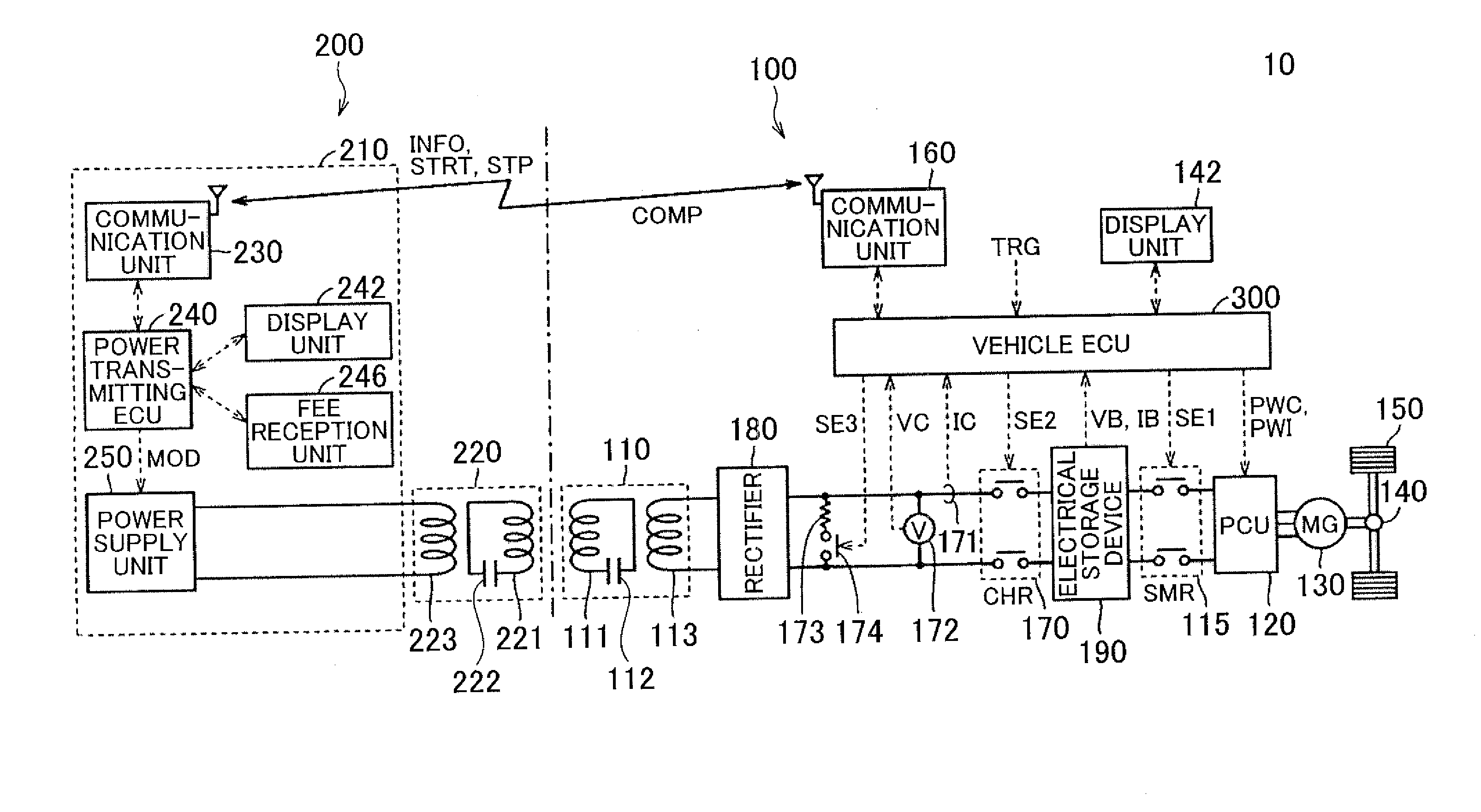
[0151]Each of the vehicles 100A, 100B transmits a message M1 to the communication unit 230 of the power transmitting device. The message M1 includes information about whether the type of the coil unit installed in the host vehicle is the circular type, the longitudinally-oriented polarized type or the laterally-oriented polarized type. The information that indicates each of coil types, that is, the circular type, the longitudinally-oriented polarized type and the laterally-oriented polarized type, is an example of information that indicates a magnetic flux passage characteristic that expresses how magnetic fluxes pass in the coil unit. Informatio...


PUM


Abstract

A power transmitting device includes: a power transmitting unit being able to contactlessly transmit electric power to a power receiving unit of a power receiving device; and a guide unit changing a guide position of the power receiving device at power reception of the power receiving device on the basis of a type of the power receiving unit. The guide unit may when the types of the power receiving and transmitting units are the same, set a position of the power receiving unit, at which center positions of the power receiving and transmitting units coincide with each other, for the guide position, and, when the types of the power receiving and transmitting units are different, set a position of the power receiving unit, at which the center positions of the power receiving and transmitting units deviate from each other, for the guide position.

Description

INCORPORATION BY REFERENCE[0001]The disclosure of Japanese Patent Application No. 2012-134953 filed on Jun. 14, 2012 including the specification, drawings and abstract is incorporated herein by reference in its entirety.BACKGROUND OF THE INVENTION[0002]1. Field of the Invention[0003]The invention relates to a contactless power transmitting device, a contactless power receiving device and a contactless power transfer system.[0004]2. Description of Related Art[0005]In recent years, a technique for contactlessly transmitting or receiving power to or from a device becomes a focus of attention because of less expense in time and effort for connection, or the like. Contactless charging is in practical use for charging a portable device, an electric vehicle, or the like.[0006]Japanese Patent Application Publication No. 2011-15549 (JP 2011-15549 A) describes an example of a position aligning technique for a contactless power transfer device for a vehicle. In this example, a spatial position...

Claims


Application Information

Patent Timeline
Patent Type & Authority Applications(United States)
IPC IPC(8): H02J7/02H02J7/00B60L50/15B60L50/16
CPCH02J7/025B60L7/14B60L15/2009B60L2210/10B60L2210/30B60L2210/40B60L2240/12B60L2240/423B60L2240/547B60L2240/549B60L2240/70B60L2250/16Y02T90/16Y02T90/14Y04S30/14Y02T10/7072B60L50/40B60L50/62B60L50/16B60L53/36B60L53/65B60L53/122B60L53/305B60L53/126H02J2310/48H02J50/90H02J7/00034Y02T10/62Y02T10/64Y02T10/70Y02T10/72Y02T90/12Y02T90/167H02J50/80H02J50/12H02J50/05
Inventor ICHIKAWA, SHINJITAKURA, TETSUYAMATSUKI, HIDETOSHISATO, FUMIHIRO
Owner TOYOTA JIDOSHA KK
Why Eureka
Try Eureka