Radio Power Transmission Apparatus and Radio Power Transmission System

a power transmission system and power transmission technology, applied in the direction of charging stations, battery/fuel cell control arrangements, transportation and packaging, etc., can solve the problem of extremely low power transmission efficiency and achieve the effect of high power transmission efficiency

Inactive Publication Date: 2015-07-16
HITACHI LTD
View PDF12 Cites 13 Cited by
  • Summary
  • Abstract
  • Description
  • Claims
  • Application Information

AI Technical Summary

Benefits of technology

[0025]In accordance with the present invention, it is possible to provide a radio power transmission apparatus, radio power transmission system, image display system, mobile-body power supplying system, radio backup power / information transmission network, and radio backup power supplying network, which are capable of transmitting power at a high power-transmission efficiency in distances where electric and magnetic fields are effective and order thereof are unignorable if compared with the wavelength.

Problems solved by technology

In this configuration, power transmission can be carried out at an extremely low power transmission efficiency.

Method used


Image

  • Radio Power Transmission Apparatus and Radio Power Transmission System
  • Radio Power Transmission Apparatus and Radio Power Transmission System
  • Radio Power Transmission Apparatus and Radio Power Transmission System

Examples


first embodiment

Configuration of the Radio Power Transmission Apparatus

[0046]As the first embodiment of the present invention, a typical configuration of the radio power transmission apparatus is explained.

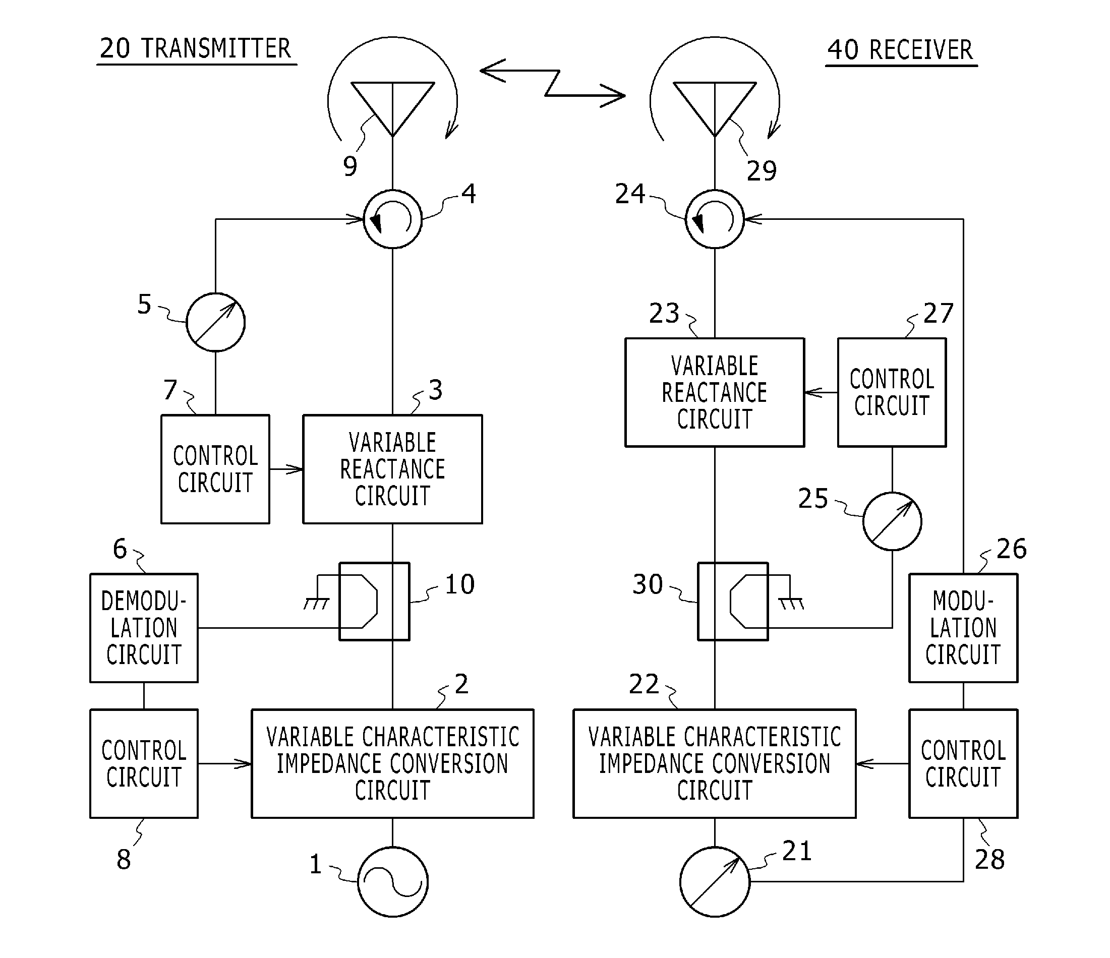
[0047]FIG. 1 is a diagram showing a typical configuration of a radio power transmission apparatus according to the first embodiment of the present invention.

[0048]In FIG. 1, power is transmitted from a transmitter 20 to a receiver 40 in a magnetic resonance state by using electromagnetic waves. A configuration combining the transmitter 20 and the receiver 40 is the radio power transmission apparatus according to the first embodiment.

Transmitter 20

[0049]In the transmitter 20, high-frequency power generated by a power generation circuit 1 is radiated to the air by a power transmitting circular polarized-wave antenna 9 through a variable transmitter characteristic impedance conversion circuit (a variable characteristic impedance conversion circuit) 2 and a variable transmitter reactance circuit (a v...

second embodiment

Configuration of the Radio Power Transmission Apparatus

[0083]Next, a second embodiment of the present invention is explained as follows.

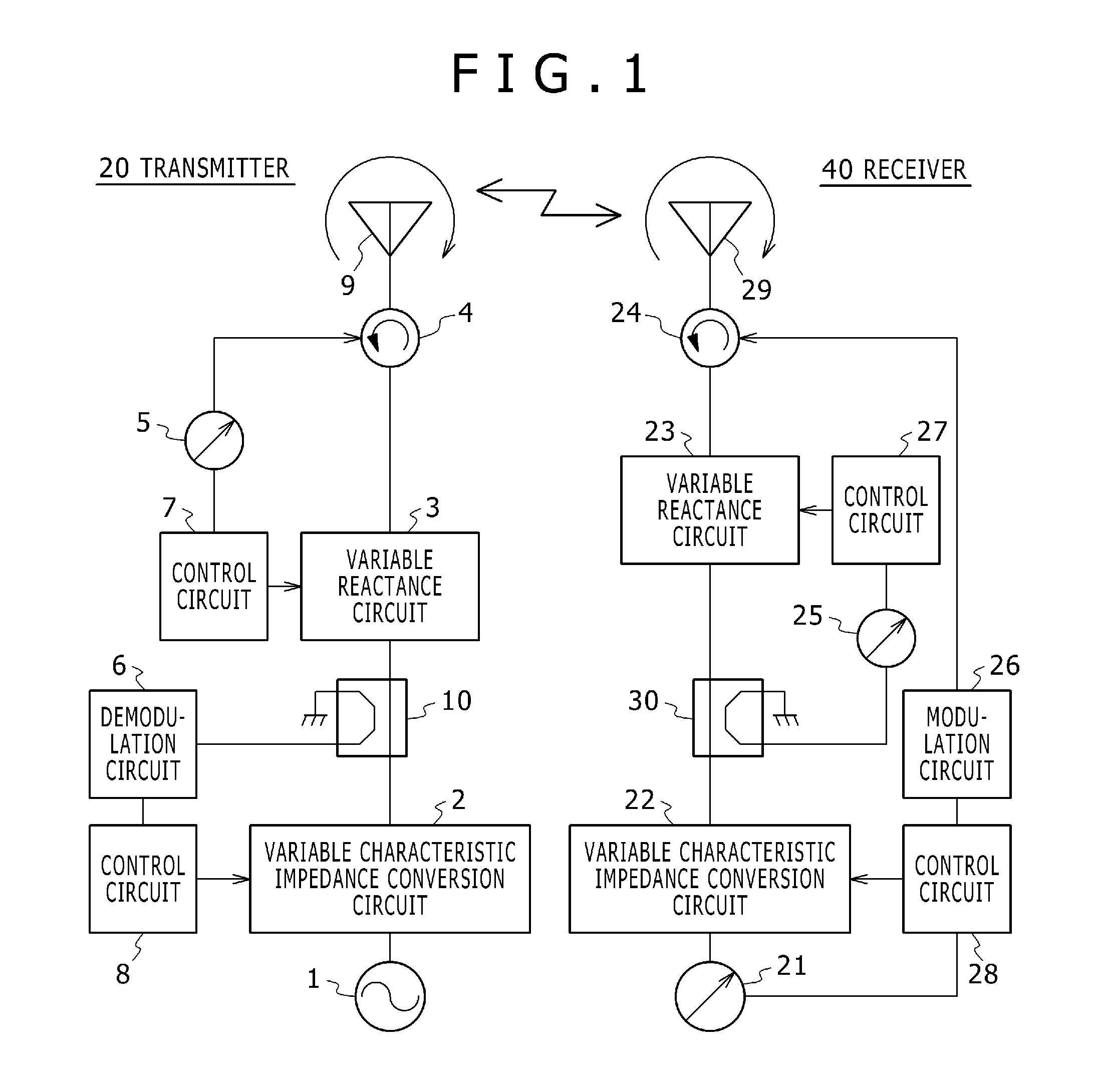
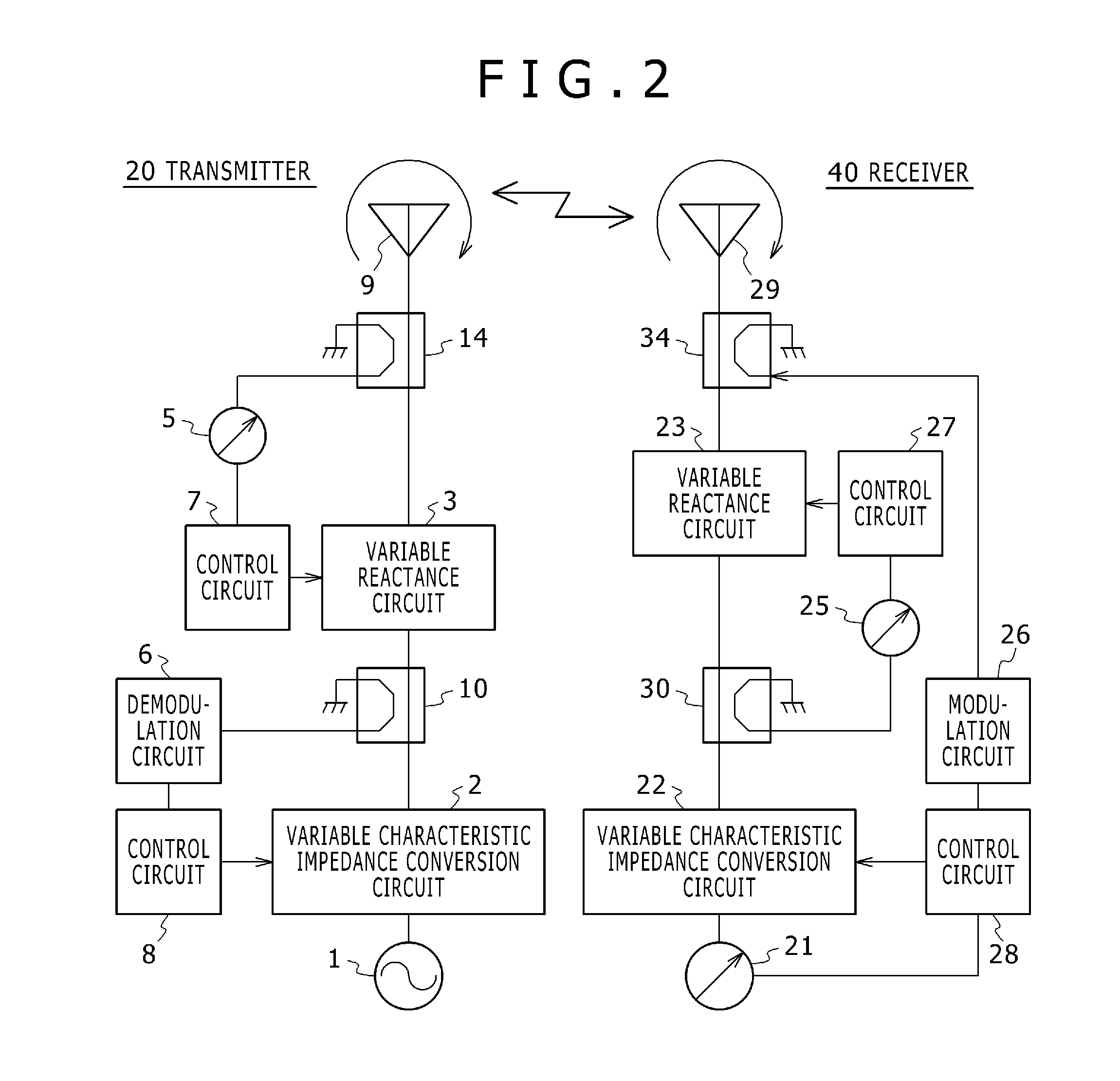
[0084]FIG. 2 is a diagram showing a typical configuration of a radio power transmission apparatus according to the second embodiment of the present invention.

[0085]FIG. 2 is different from FIG. 1 in that, in place of the power transmitting circulator 4 (shown in FIG. 1) and the power receiving circulator 24 (also shown in FIG. 1), a second power transmitting directivity coupler 14 and a second power receiving directivity coupler 34 are used.

[0086]It is necessary to decrease the degree of coupling between the second power transmitting directivity coupler 14 and the second power receiving directivity coupler 34 to a value which reduces the effect on the efficiency of the power transmission from the transmitter to the receiver. For example, a value in a range of −10 dB to −20 dB is used.

[0087]In accordance with the second embodiment, the directivity co...

third embodiment

Configuration of the Radio Power Transmission Apparatus

[0092]Next, a third embodiment of the present invention is explained as follows.

[0093]FIG. 3 is a diagram showing a typical configuration of a radio power transmission apparatus according to the third embodiment of the present invention.

[0094]FIG. 3 is different from FIG. 1 in that omitted elements include the power transmitting circulator 4, the power receiving circulator 24, the transmitted power measurement circuit 5, and the received power measurement circuit 25.

[0095]In addition, the added element is a power receiving demodulation circuit 31 (a second demodulation circuit).

[0096]In addition, elements are modified as follows. The first power transmitting control circuit 7 for controlling the variable transmitter reactance circuit 3 executes the control by an output signal of the power transmitting demodulation circuit 6 (a first demodulation circuit) and the first power receiving control circuit 27 for controlling the variab...


PUM


Abstract

A radio power transmission apparatus comprises a transmitter 20 having a power transmitting antenna 9 for transmitting electromagnetic waves and a power transmitting circuit and a receiver 40 having a power receiving antenna 29 for receiving electromagnetic waves and a power receiving circuit. In the radio power transmission apparatus, on the basis of power reflected to the power transmitting antenna 9, the power transmitting circuit executes control to change the circuit reactance of the power transmitting circuit in order to control the imaginary part of power of the electromagnetic waves to be transmitted. In addition, on the basis of a value of power transmitted to the transmitter 20 by using electromagnetic waves of power transmission used by the receiver 40 to transmit a value of power received by the receiver 40 through the power receiving antenna 29, the power transmitting circuit executes control to change the circuit reactance of the power transmitting circuit or the characteristic impedance of the power transmitting circuit in order to control the real part of power of the electromagnetic waves to be transmitted.

Description

TECHNICAL FIELD[0001]The present invention relates to a radio power transmission apparatus for transmitting power to a remote destination in a non-contact way by using electromagnetic waves. More specifically, the invention relates to a radio power transmission system, image display system, mobile-body power supplying system, radio backup power / information transmission network, radio backup power supplying network that utilize the apparatus.BACKGROUND ART[0002]The non-contact power transmission can be carried out by using an electromagnetic phenomenon related to magnetic waves. Depending on the relative relation between the positions of the power transmitting side and the power receiving side, a number of methods have been put to practical use.[0003]If the distance between the power transmitting side and the power receiving side is very short, high-efficiency power transmission can be carried out by electromagnetic induction using mainly a magnetic field.[0004]For example, a cooking...

Claims


Application Information

Patent Timeline
Patent Type & Authority Applications(United States)
IPC IPC(8): H02J17/00H04B5/00H02J5/00
CPCH02J17/00H04B5/0037H02J5/005B60L2210/30B60L2210/40B60L2240/70Y02T90/16Y02T90/14Y04S10/126Y04S30/14B60L53/12B60L53/36B60L53/63B60L53/65B60L58/21B60L53/305H02J50/12H02J50/90Y02E60/00Y02T10/70Y02T10/7072Y02T10/72Y02T90/12Y02T90/167H02J50/27H02J50/23H02J50/40H02J50/80H02J50/20
Inventor TAKEI, KEN
Owner HITACHI LTD
Why Eureka
Try Eureka