

2d/3d switchable display device and method for manufacturing the same
a display device and switchable technology, applied in the direction of static indicating devices, measurement devices, instruments, etc., can solve the problems of affecting the quality of 3d image display, the conformity rate will decrease, and the inability to display excellent stereoscopic effects, so as to reduce viewers' discomfort, increase the tolerance of alignment errors, and increase the stereoscopic effect
- Summary
- Abstract
- Description
- Claims
- Application Information
AI Technical Summary
Benefits of technology
Problems solved by technology
Method used
Image

Examples
first embodiment
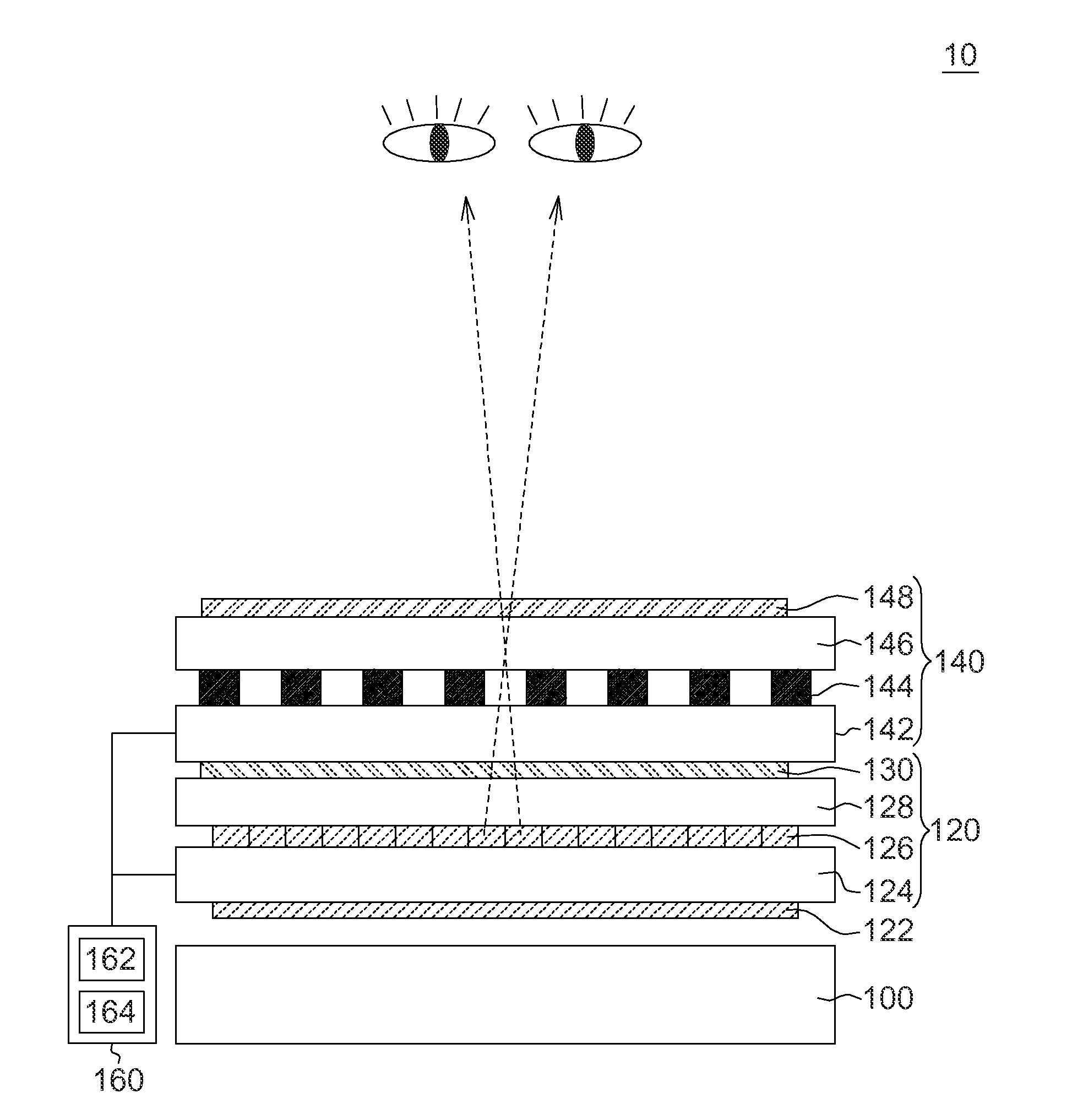
[0050]Referring to FIG. 2A, a 2D / 3D switchable 2D / 3D switchable display device 10 according to an embodiment of the invention is shown. As indicated in FIG. 2, the 2D / 3D switchable display device 10 comprises a backlight module 100, a display module 120, an optical control module 140 and a driving module 160. In the present embodiment, the optical control module 140 is exemplified by parallax barrier design. The display module 120 is located at one side of the optical control module 140, and the position of the display module 120 and that of the optical control module 140 are exchangeable. In the present embodiment, the optical control module 140 is disposed between the display module 120 and the viewer, and the display module 120 is disposed between the optical control module 140 and the backlight module 100. In other embodiments, the position of the display module 120 is exchangeable with that of the optical control module 140. The display module 120 and the optical control module...
second embodiment
[0079]FIG. 8A shows a schematic diagram of the generation of an initial view matrix table Sj(N) according to a second embodiment of the invention. The initial view matrix table S(N) is a matrix table generated by the sampling method of the view pixel information Vd(N) of the first embodiment. The initial view matrix table Sj(N) is another matrix table generated by the sampling method of the view pixel information Vd(N) of the present embodiment. The difference between the two initial view matrix tables S(N) and Sj(N) lies in that in the present embodiment only a portion of the view frame V(N) is used, and the view frames V(N) are numbered and N view frames V(N) are provided by way of reverse replacement. The number of view frames V(N) provided is the same as the number of view angles N. The present embodiment can avoid 3D image jumping which arises when the parallax of the view frames received by the two eyes is reversed. When the number of view angles N is an even number, the numbe...
third embodiment
[0085]FIG. 10 shows a schematic diagram of a plurality of optical controlling elements 1022, 1024 and 1026 (similar to the transparent area 140C but with a boundary being a straight line) of the optical control module 140 arranged at different arrangement angles according to an embodiment of the invention. As indicated in FIG. 10, the pixel matrix 102 disposed on the display module 120 has a plurality of sub-pixels 1020, each (such as R sub-pixel, G sub-pixel and B sub-pixel) having a length h and a width w. With respect to the sub-pixels 1020, the arrangement of the optical controlling elements 1022 is based on a slope being w / h. With respect to the sub-pixels 1020, the arrangement of the optical controlling elements 1024 is based on a slope being 2w / 3h. With respect to the sub-pixels 1020, the arrangement of the optical controlling elements 1026 is based on a slope being w / 3h.
[0086]In other words, the slope can be expressed as
a×wb×h,
wherein a, b both are a positive integer. Moreov...
PUM
| Property | Measurement | Unit |
|---|---|---|
| Angle | aaaaa | aaaaa |
| Angle | aaaaa | aaaaa |
| Weight | aaaaa | aaaaa |
Abstract
Description
Claims
Application Information