Electrical junction box

a junction box and electric technology, applied in the direction of electrical apparatus casings/cabinets/drawers, substation/switching arrangement details, casings/cabinets/drawers details, etc., can solve the problems of water bouncing against the waterproof wall and being restricted so as to prevent water from infiltrating into the water draining hole

Active Publication Date: 2013-12-19
YAZAKI CORP
View PDF8 Cites 10 Cited by
  • Summary
  • Abstract
  • Description
  • Claims
  • Application Information

AI Technical Summary

Benefits of technology

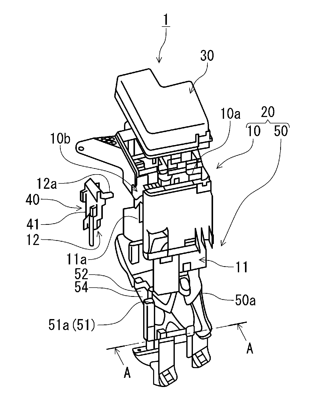
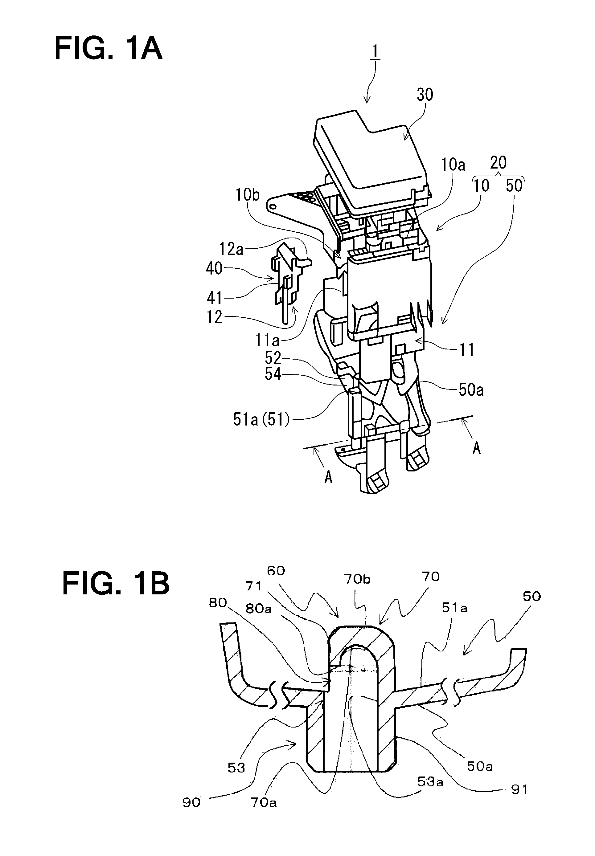
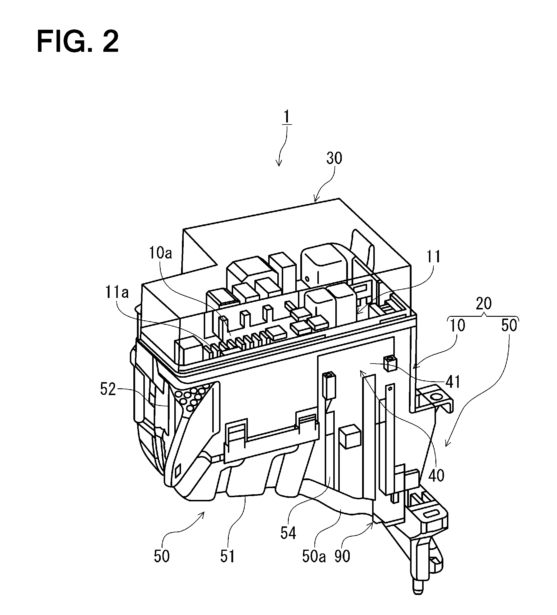
This patent is about an electrical junction box that is designed to prevent water from getting inside and damaging the electrical components. The box has a curved surface that prevents water from bouncing around and getting into the drainage hole. The box also has a spherical cover wall part that allows water to smoothly contact and drain out of the box. This design prevents water from getting inside and causing issues with the electrical system.

Problems solved by technology

Therefore, water bouncing against the waterproof wall, which is provided inside the water draining hole along the periphery thereof, is restricted from infiltrating into the water draining hole.

Method used


Image

  • Electrical junction box
  • Electrical junction box
  • Electrical junction box

Examples


first modified embodiment

[0066]Next, a first modified embodiment of the electrical junction box 1 according to the former embodiment of the present invention will be described with reference to FIG. 9. FIG. 9 is a sectional view of the major surroundings of a water draining hole 53 of an electrical junction box 2 according to the first modified embodiment of the former embodiment 1 of the present invention when obliquely viewed from an upper portion of the inside of a lower cover section 100.

[0067]The electrical junction box 2 of the first modified embodiment is different from the electrical junction box 1 of the former embodiment in that the lower cover section 100 includes a waterproof wall 110, instead of the waterproof wall 60, and a spherical cover wall part 120 is not a dome-type wall.

[0068]The other configuration is identical to that of the former embodiment, and like reference signs indicate like elements in the former embodiment.

[0069]The spherical cover wall part 120 stands up from a periphery 53a...

second modified embodiment

[0071]Next, a second modified embodiment of the electrical junction box 1 according to the former embodiment of the present invention will be described with reference to FIG. 10. FIG. 10 is a view of the major surroundings of a water draining hole 53 of an electrical junction box 3 according to the second modified embodiment of the former embodiment 1 of the present invention when obliquely viewed from a lower side of a lower cover section 200.

[0072]The electrical junction box 3 of the second modified embodiment is different from the electrical junction box 1 of the former embodiment in that the lower cover section 200 does not includes the peripheral draining protrusion 90.

[0073]The other configuration is identical to that of the former embodiment, and like reference signs indicate like elements in the former embodiment.

[0074]In the electrical junction box 3 according to the second modified embodiment, like the electrical junction box 1 of the former embodiment, water bounces again...


PUM


Abstract

An electrical junction box includes a box body in which electrical parts are mounted and that has a water draining hole provided at a bottom wall part of the box body and a waterproof wall that is provided inside the box body along a periphery of an opening of the water draining hole. The waterproof wall includes a spherical cover wall part standing from the periphery of the water draining hole to cover the water draining hole with an inner spherical surface, and a draining opening part formed at a portion of the spherical cover wall part to allow water exist in the box body to drain to the outside of the box body through the water draining hole.

Description

CROSS REFERENCE TO RELATED APPLICATION[0001]This application is based on Japanese Patent Applications No. 2012-129831 filed on Jun. 7, 2012, the contents of which are incorporated herein by reference.BACKGROUND OF THE INVENTION[0002]1. Technical Field[0003]The invention relates, in general, to an electrical junction box having a water draining hole on a bottom wall part of a box body in which electrical parts are contained.[0004]2. Background Art[0005]Conventionally, an electrical junction box, in which electrical parts such as connectors, relays, fuses, or the like are intensively integrated, is mounted in an engine room to supply electric power to electronic appliances mounted e.g. in a vehicle. Proposed has been an electrical junction box in which a water draining hole is formed on a bottom wall part of a box body thereof to prevent the infiltration of water into the box body in which electrical parts are mounted (see e.g. JP-A-08-322124).[0006]The electrical junction box disclos...

Claims


Application Information

Patent Timeline
IPC IPC(8): H05K5/02
CPCH05K5/0239H02G3/088H05K5/03
Inventor MAKINO, MASAHIROKAWAI, TAKANORIISHIHARA, YOSHIYUKI
Owner YAZAKI CORP
Why Eureka
Try Eureka