Compression bone screw

a bone screw and compression technology, applied in the field of bone screw fixation in orthopaedic surgery, can solve the problems of poor quality bone material, inability to easily control the amount of compression provided, and reducing the degree of embedding of the leading element within the distal bone fragmen

Inactive Publication Date: 2013-12-19
YALIZIS MATTHEW ADAM
View PDF2 Cites 64 Cited by
  • Summary
  • Abstract
  • Description
  • Claims
  • Application Information

AI Technical Summary

Benefits of technology

[0034]In at least one embodiment, first and second primary detents are provided at the end of said first and second shank portions respectively for engaging said first element and said second element respectively during said first mode of operation, thereby enabling said shank to be rotationally driven in unison with said first element and said second element in said first mode of operation, said second shank thread being opposite handed to said second element external thread.
[0045]In one form first and second primary detents are provided at the end of said first and second shank portions respectively for engaging said first element and said second element respectively during said first mode of operation, thereby enabling said shank to be rotationally driven in unison with said first element and said second element in said first mode of operation, said second shank thread being opposite handed to said second element external thread.
[0046]In one form, first and second secondary detents are provided between said first and second shank portions for engaging said first element and said second element respectively upon completion of said second mode of operation, thereby limiting movement of said first element towards said second element.

Problems solved by technology

The amount of compression provided, however, cannot be readily controlled and is entirely dependent upon the thread pitch differentiation and the depth to which the screw must be embedded to provide adequate purchase on the distal and proximal bone fragments.
With this arrangement, however, the second action, tending to continue driving the leading element through the distal fragment, may result in the leading element projecting from the distal surface of the distal bone fragment and reducing the degree of embedment of the leading element within the distal bone fragment.
The typical coarse pitch thread, designed to cut into the bone material, may also result in failure in poor quality bone material when attempting to generate significant compression loads by driving the coarse steel thread further through the bone.
The coarse thread also limits the degree of control of the amount of compression applied.

Method used


Image

  • Compression bone screw
  • Compression bone screw
  • Compression bone screw

Examples


first embodiment

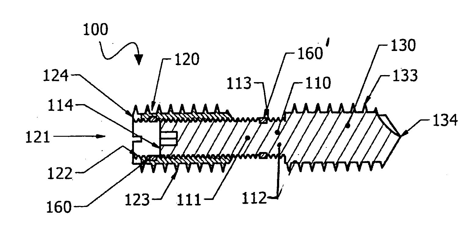
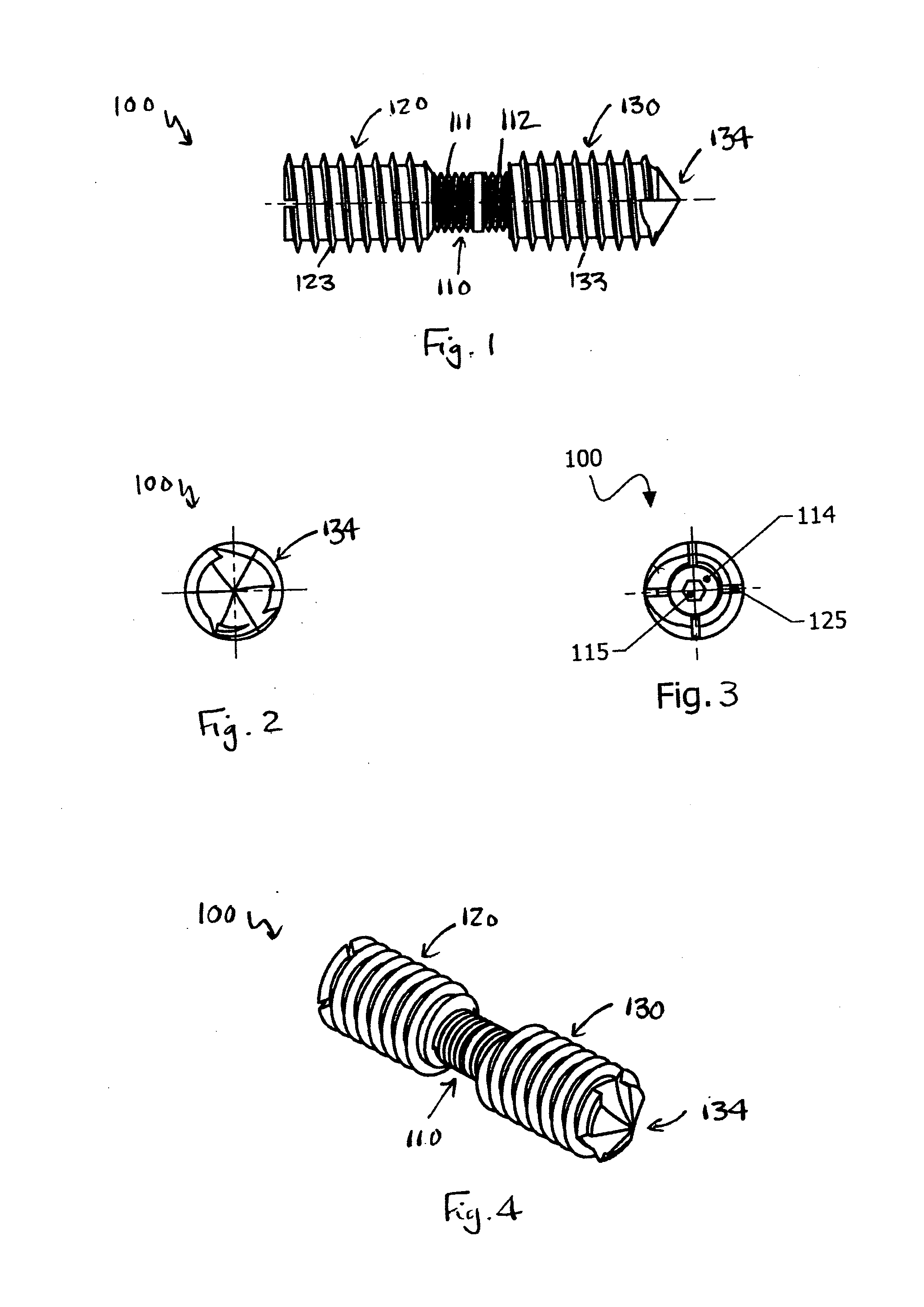
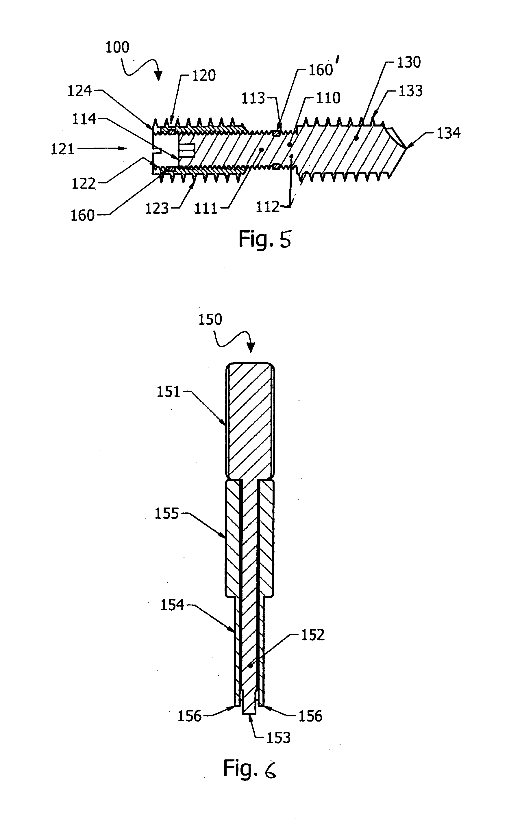
[0099]A compression bone screw 100 is depicted in FIGS. 1 to 5. The compression bone screw 100 comprises a shank 110, a first element 120 and a second element 130.

[0100]The shank 110 has longitudinally opposing first and second shank portions 111, 112. The first shank portion 111 is externally threaded with a first shank thread 113 that is here a left-handed thread. In the arrangement depicted, the shank 110 has an overall diameter of approximately 6 mm and the first shank thread 113 has a relatively fine pitch of approximately 1 mm.

[0101]The first element 120 has a first element aperture 121 longitudinally extending therethrough and a first element internal thread 122 formed on the wall of the first element aperture 121. The first element 120 is threadingly mounted on the first shank portion 111 by way of the first element internal thread 122 threadingly engaging the first shank thread 113. Accordingly, the first element internal thread 122 and first shank thread 113 are matching ...

second embodiment

[0107]An alternate configuration is envisaged where the first element 120 forms the leading element and the second element 130 forms the trailing element. In such a configuration however, the first element 120, being the element threadingly mounted on the shank 110, would not be as accessible for access by a drive tool for driving the first element 120 in unison with the first shank portion 111. As an alternative, the first element 120 could be releasably fixed to the first shank portion 111 for the first mode of operation in a similar manner to that described below in relation to the

[0108]The fixing of proximal and distal bone fragments 1, 2 of a fractured bone using the compression bone screw 100 of the first embodiment will now be described with reference to FIGS. 7 and 8.

[0109]With the proximal and distal bone fragments 1, 2 appropriately positioned, a guide hole 3 with a diameter of approximately 8 mm for the arrangement depicted is first drilled through both the proximal and d...

fourth embodiment

[0155]As will be appreciated from the representations, the non-threaded third shank portion 570 has an increased length compared to that of the third shank portion 470 of the compression bone screw 400 of the fourth embodiment, having a sufficient length to extend through the thickness of the proximal bone fragment 1 in operation.

[0156]The first shank portion 511 is of identical configuration to the first shank portion 411 of the compression bone screw 400 of the fourth embodiment, except that it has a shortened length in keeping with the shortened length of the first element 520. The first shank portion 511 is externally threaded with the first shank thread 513 which, in the arrangement depicted, is again a right-handed thread which is opposite-handed to the left-handed second shank thread 516. The first shank portion 511 is again provided with the first primary detent 518 in the form of a first enlarged head formed on the end of the first shank portion 511. A first secondary deten...


PUM


Abstract

A compression bone screw (100) comprises a shank (110), a first element (120) and a second element (130). The shank (110) has longitudinally opposing first and second shank portions (111, 112). The first shank portion (111) is externally threaded with a first shank thread (113). The first element (120) is threadingly mounted on the first shank portion (111) by way of a first element internal thread (122) threadingly engaging the first shank thread (113). The first element (120) is externally threaded with a first element external thread (123). The second element (130) is mounted on, or integrally formed with, the second shank portion (112). The second element (130) is externally threaded with a second element external thread (133). The second element external thread (133) and the first element external thread (123) are like-handed. The first shank portion (111) and the first element (120) are configured to operate in a first mode of operation in which the shank (110) and the first element (120) are rotationally driven in unison and a second mode of operation in which the shank (110) is rotationally driven independent of the first element (120), such that the first element (120) moves along the first shank portion (111) towards the second element (130).

Description

TECHNICAL FIELD[0001]The present invention relates to the field of bone fixation in orthopaedic surgery and in particular relates to a compression bone screw.BACKGROUND OF THE INVENTION[0002]Compression bone screws are used in orthopaedic surgery for bone fixation, and in particular to fix two fragments of a fractured bone and for fixation of osteotomies and arthrodeses. Healing of fractured bones is greatly improved with the application of compression between the bone fragments.[0003]Various forms of compression bone screw have previously been proposed seeking to provide such compression between bone fragments. One form of known compression bone screw, known as the Herbert screw, utilises external leading and trailing threads on the screw for embedment within distal and proximal bone fragments. The leading and trailing external threads are like-handed, but are of unequal pitch, with a greater pitch on the leading thread. This advances the screw through the distal bone fragment at a...

Claims


Application Information

Patent Timeline
Patent Type & Authority Applications(United States)
IPC IPC(8): A61B17/86
CPCA61B17/8625A61B17/68A61B17/7225A61B17/8685A61B17/8875
Inventor YALIZIS, MATTHEW ADAM
Owner YALIZIS MATTHEW ADAM
Why Eureka
Try Eureka