Substrate joining method using rivet, and joining structure

a technology of rivets and joining structures, applied in the direction of threaded fasteners, screws, mechanical devices, etc., can solve the problems of reducing weight, requiring a long time for adhesive hardening, and no method of joining in a short time, so as to prevent the progress of separation or cracks, suppress stress concentration, and suppress the effect of cracks

Inactive Publication Date: 2013-12-26
NIHON UNIVERSITY
View PDF20 Cites 43 Cited by
  • Summary
  • Abstract
  • Description
  • Claims
  • Application Information

AI Technical Summary

Benefits of technology

[0019]The joining method of the plate materials using the rivet according to the present invention, because of the above-mentioned means, uses the seat member having the inner hole as a jig at the time of the punching, to surely carry out the punching by means of the rivet and suppress stress concentration and the like generated in the plate materials by the rivet. This suppresses separation or cracks of the plate materials at the time of the punching.
[0020]After the joining, the seat member is left to prevent progress of separation or cracks that may be generated around a pierced portion by means of the rivet.
[0021]The joining structure of the plate materials using the rivet according to the present invention, because of the above-mentioned means, prevents progress of separation or cracks that may be generated around a pierced portion by means of the rivet after the fastening and the joining.

Problems solved by technology

However, there is no method of joining in a short time with ease like spot welding for the metal.
This is one of factors to frustrate the weight reduction due to the material substitution.
However, there are problems such that an adhesive requires a long time to be hardened in view of productivity in the automobile industry, and joining surfaces require to be processed and cleaned to result in high cost.
Further, there is a problem in heat resistance, influence of moisture absorbent, weakness under cool environment or fast deformation, and the like.
However, there are problems such that it requires a long time for a hole making process, and a tool becomes worn early compared with that for metal or the like.
However, the method drives the rivet body into the metal plate and plastically deforms the metal plate, so that the FRP plates may be separated from each other and get cracked around the rivet body according to the plastic deformation.
This is the broadly possible problem in joining laminated plate materials, thin plate materials, or the like by driving a rivet.
That is not necessarily possible problem in only the SPR and is the broadly possible problem in joining by driving a rivet.

Method used


Image

  • Substrate joining method using rivet, and joining structure
  • Substrate joining method using rivet, and joining structure
  • Substrate joining method using rivet, and joining structure

Examples


embodiment 1

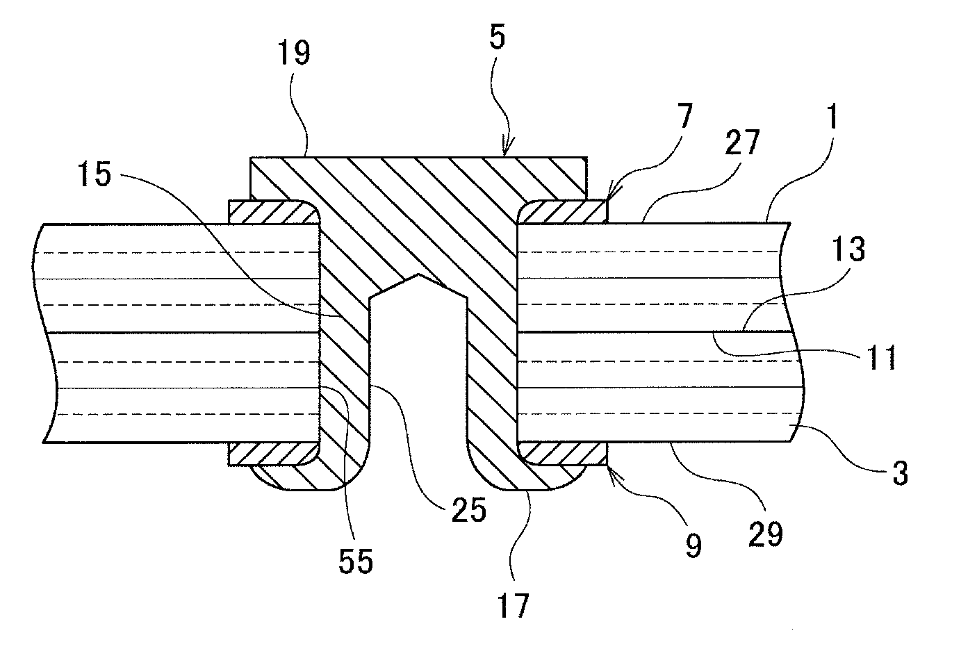
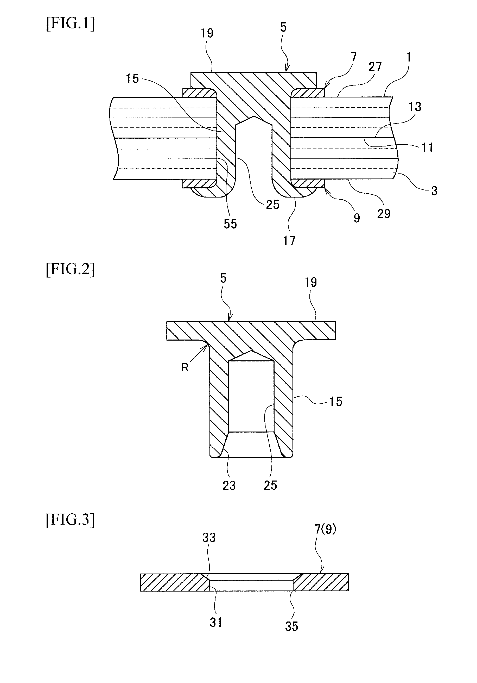
[0039]FIG. 1 is a sectional view of a joining structure of plate materials. In addition, top and bottom, and left and right are hereinafter assumed as top and bottom, and left and right at the time of punching and joining processes by means of a self-piercing rivet (SPR).

[0040]The joining structure of the plate materials uses laminated plate materials 1 and 3 made of, for example, carbon fiber reinforced plastic (CFRP) as plate materials that are fastened and joined together by a SPR 5 through washers 7 and 9 as top and bottom seat members.

[0041]The laminated plate materials 1 and 3 are laid one on another with joining surfaces 11 and 13 being in contact with each other, and the washers 7 and 9 are arranged in contact with respective opposite surfaces 27 and 29 relative to the joining surfaces of the plate materials 1 and 3. The washers 7 and 9 each are a doughnut-shaped flat plate having an inner hole 31.

[0042]The SPR 5 as the rivet has a rivet, head portion 19 and a rivet shaft po...

embodiment 2

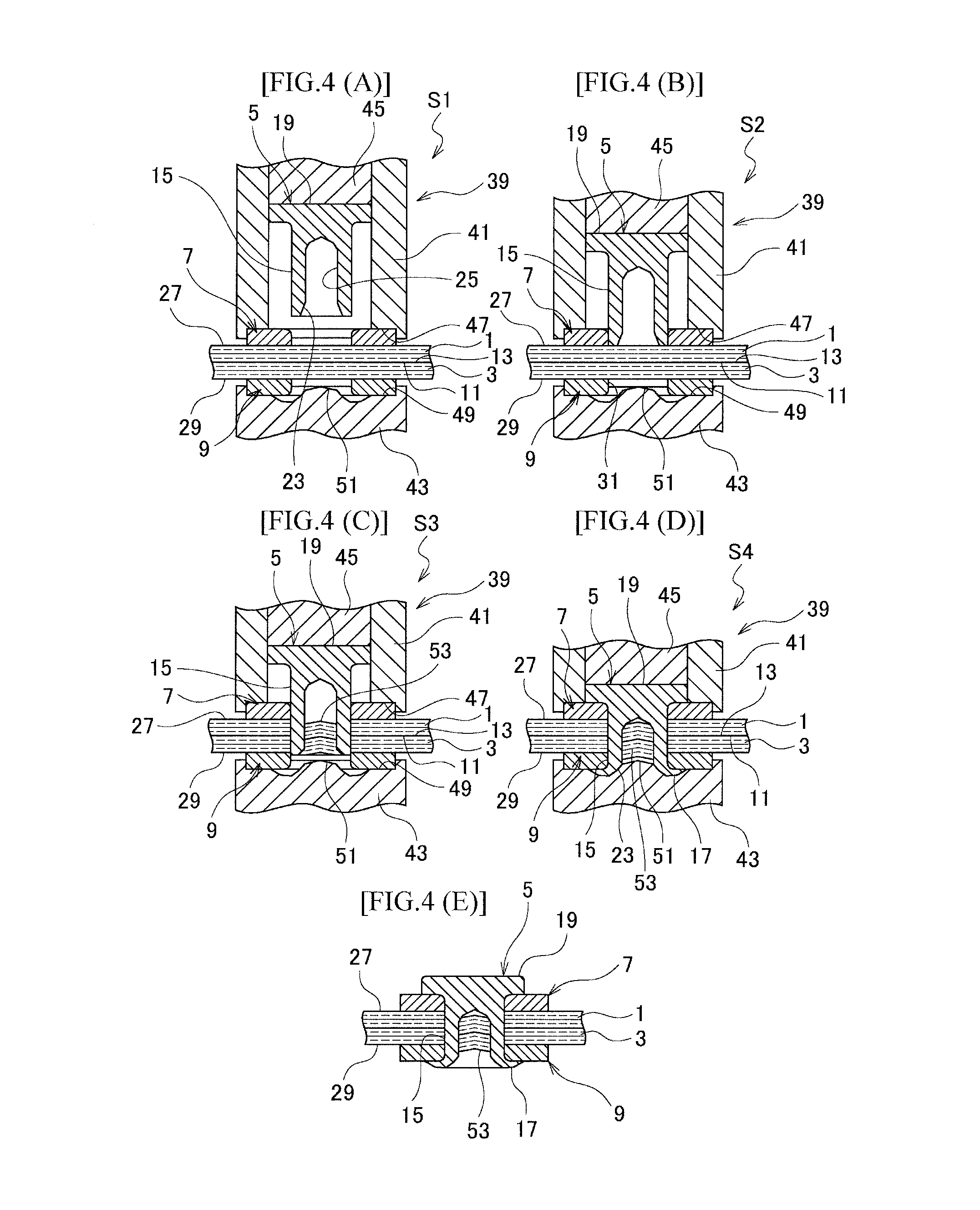
[0118]FIG. 12 shows sectional views illustrating a joining process in which (A) is a waiting step, (B) a punching start step, (C) a punching step, (D) a crimp waiting step, (E) a crimping step, and (F) a state after joining.

[0119]In a joining method and joining structure of plate materials using a rivet according to this embodiment 2, a rivet shaft portion 15E of a SPR 5D is solid and crimping of the rivet shaft portion 15E is press-crimping or spin-crimping. At an outer periphery of a front edge of the rivet shaft portion 15E is C-chamfered. The C-chamfering may be omitted.

[0120]The joining process of FIG. 12 uses a joining apparatus 67. In the joining apparatus 67, a lower punch 69 is changed with respect to the joining apparatus 39 of FIG. 4 and a press punch (or rotary punch) 71 for crimping is used as a replacement for the lower punch 69.

[0121]The punch 69 is a hollow shape, has a washer support recessed portion 49 formed on a top surface thereof, and has an outlet hole 71 for ...

embodiment 3

[0130]FIGS. 13 and 14 are sectional views illustrating a joining structure of plate materials according to the embodiment 3. The basic structure is the same as that, of the embodiment 1, and therefore, the same parts are represented with the same reference numerals and corresponding parts are represented with the same reference numerals with “F” to omit a duplicative explanation.

[0131]The joining structure of FIG. 13 uses, for example, a metal plate 3F and a laminated plate material 3 made of carbon fiber reinforced plastic (CFRP) as plate materials joined and fastened together using a SPR 5F through a washer 9 as a bottom seat member. As the metal plate 1F, a steel panel, stainless steel panel, duralumin panel, aluminum alloy panel may be used, but the material is not limited thereto. In addition, a washer as a top seat member on the metal plate 1F side may be concurrently used.

[0132]The joining structure of FIG. 14 uses, for example, a laminated plate material 1 made of carbon fib...


PUM

PropertyMeasurementUnit
stress concentrationaaaaaaaaaa
thicknessaaaaaaaaaa

Abstract

A joining method includes punching respective laminated plate materials by a rivet shaft portion of a SPR, forming a crimp portion at the front end of the rivet shaft portion, and fastening and joining the laminated plate materials between the rivet head portion and the crimp portion. Washers are laid on and brought into contact with respective opposite surfaces relative to joining surfaces of the laminated plate materials, the washers each having an inner hole through which the rivet shaft portion is allowed to pass, the washers are used as jigs at the time of the punching, the punching by means of the rivet shaft portion is performed along the inner holes of the washers, and the joining is performed so that the washers left between the rivet head and the crimp portion and the opposite surfaces.

Description

TECHNICAL FIELD[0001]The present invention relates to a substrate joining method using a rivet and a joining structure, for punching and joining laminated plate materials, thin plate materials or the like by means of the rivet.BACKGROUND ART[0002]Carbon fiber reinforced plastic (CFRP) is superior in terms of specific rigidity, specific strength, fatigue property, and corrosive property compared with metal, and is examined to be applied to structural members of automobiles or the like for the sake of weight reduction.[0003]However, there is no method of joining in a short time with ease like spot welding for the metal. This is one of factors to frustrate the weight reduction due to the material substitution.[0004]In this regard, adhesive joining is generally used to join laminated plate materials made of CFRP.[0005]However, there are problems such that an adhesive requires a long time to be hardened in view of productivity in the automobile industry, and joining surfaces require to b...

Claims


Application Information

Patent Timeline
Patent Type & Authority Applications(United States)
IPC IPC(8): B21J15/02F16B19/08
CPCB21J15/02F16B19/08F16B5/04F16B19/086B21J15/025B29C65/562B29C65/602B29C65/7437B29C65/8253B29C66/1122B29C66/21B29C66/43B29C66/721B29C66/7212B29C66/81422B29C66/81423B29C66/81429B29C66/8322B29C66/72143B29C66/7392B29C66/7394Y10T29/49956B21J15/147B29K2307/04B29K2309/08
Inventor UEDA, MASAHITOHASEGAWA, HIROYUKIWATANABLE, KINYAFUJII, NAOYA
Owner NIHON UNIVERSITY
Why Eureka
Try Eureka