Electric re-heat dehumidification

a dehumidification and electric heating technology, applied in the direction of domestic cooling devices, lighting and heating devices, heating types, etc., can solve the problems of excessive humidity, uncontrollable indoor humidity, and detriment to comfort and indoor air quality

Active Publication Date: 2013-12-26
CARRIER CORP
View PDF6 Cites 4 Cited by
  • Summary
  • Abstract
  • Description
  • Claims
  • Application Information

AI Technical Summary

Benefits of technology

[0005]According to one aspect of the invention, an electric re-heat dehumidification apparatus to dehumidify a conditioned space is provided and includes a conditioning unit to produce an output airstream including overcooled air to be provided to the conditioned space to overcool the conditioned space during the dehumidifying of the conditioned space, a resistive element disposed within an output airstream of the conditioning unit, which, when activated, heats the overcooled air of the output airstream and a controller, operably coupled to the resistive element, to activate the resistive element in accordance with information of the conditioning unit, the resistive element and a temperature of the conditioned space to limit the overcooling of the conditioned space.
[0006]According to another aspect of the invention, an electric re-heat dehumidification apparatus to dehumidify a conditioned space is provided and includes a conditioning unit to produce an output airstream including overcooled air to be provided to the conditioned space to overcool the conditioned space during the dehumidifying of the conditioned space, a user interface by which an occupant of the conditioned space inputs commands governing conditioning unit operation, a resistive element disposed within an output airstream of the conditioning unit, which, when activated, heats the overcooled air of the output airstream and a controller, operably coupled to the resistive element, to activate the resistive element in accordance with the input commands, information of the conditioning unit and the resistive element and a temperature of the conditioned space to limit the overcooling of the conditioned space.

Problems solved by technology

Indoor humidity levels, therefore, remain uncontrolled and often become excessive, to the detriment of comfort and indoor air quality.

Method used


Image

  • Electric re-heat dehumidification
  • Electric re-heat dehumidification
  • Electric re-heat dehumidification

Examples


Embodiment Construction

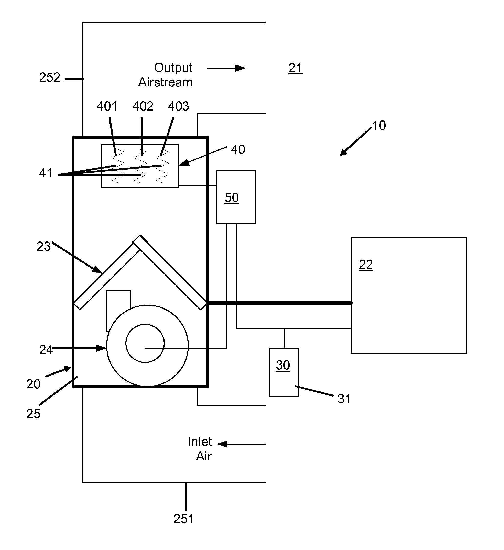
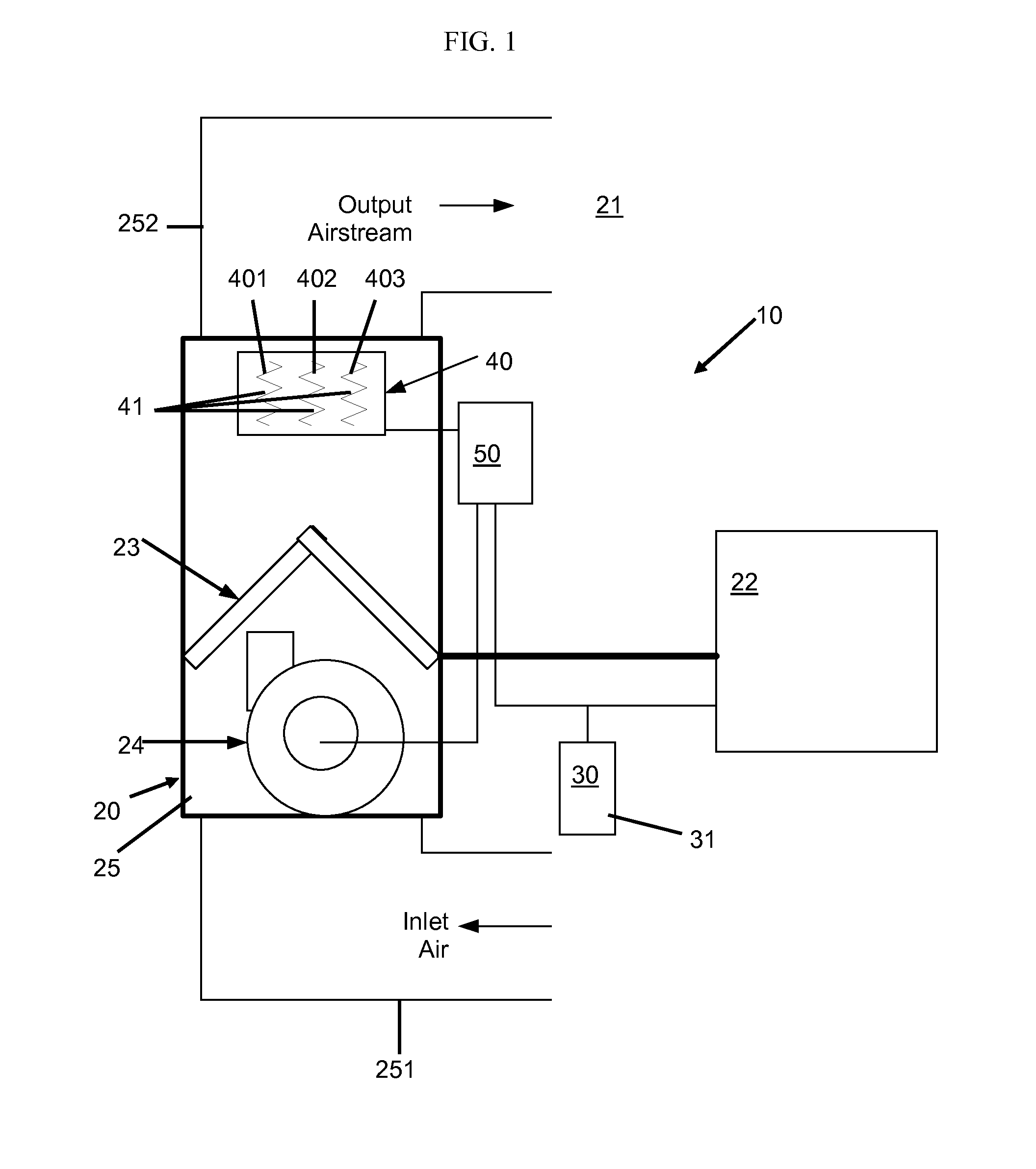
[0014]With reference to FIG. 1, an electric re-heat dehumidification apparatus 10 is provided. The apparatus 10 includes a conditioning unit 20, a user interface 30, a resistive element 40 and a controller 50. The conditioning unit 20 may be a wall unit air conditioner, a central air conditioning unit, a heat pump or an HVAC system and is configured to provide conditioned air to a conditioned space 21, which may be an enclosed space. In some cases, this conditioned air serves to overcool the conditioned space 21 during a dehumidification process. The user interface 30 is operably coupled to the conditioning unit 20 and may be a thermostat that is accessible to an occupant of the conditioned space 21. The user interface 30 may therefore be used by the occupant to input commands governing operation of the conditioning unit 20. The resistive element 40 is disposed within or proximate to an output airstream of the conditioning unit 20 and, when activated, heats the output airstream. The...


PUM


Abstract

An electric re-heat dehumidification apparatus to dehumidify a conditioned space is provided and includes a conditioning unit to produce an output airstream including overcooled air to be provided to the conditioned space to overcool the conditioned space during the dehumidifying of the conditioned space, a resistive element disposed within an output airstream of the conditioning unit, which, when activated, heats the overcooled air of the output airstream and a controller, operably coupled to the resistive element, to activate the resistive element in accordance with information of the conditioning unit, the resistive element and a temperature of the conditioned space to limit the overcooling of the conditioned space.

Description

CROSS REFERENCE TO RELATED APPLICATION[0001]This application is a National Stage Application of PCT Application No. PCT / US12 / 28165 filed Mar. 8, 2012, which is a PCT Application of U.S. Provisional Patent Application No. 61 / 451316 filed Mar. 10, 2011, the disclosures of which are incorporated by reference herein in their entireties.BACKGROUND OF THE INVENTION[0002]The subject matter disclosed herein relates to electric re-heat dehumidification and, more particularly, to an electric re-heat dehumidification apparatus.[0003]Heating, Ventilation and Air Conditioning (HVAC) systems enhance dehumidification in high humidity climates by removing moisture from indoor air even during cool night periods and the spring / fall shoulder seasons when high indoor humidity levels are coupled with moderate cooling loads. In these situations, since indoor temperatures remain at comfortable levels most of the time, typical thermostat based systems operate in the air conditioning mode for limited, if an...

Claims


Application Information

Patent Timeline
Patent Type & Authority Applications(United States)
IPC IPC(8): F24F3/153
CPCF24F3/153F24F2003/1446F24F2221/34
Inventor PURANEN, CHRISSHAH, RAJENDRA K.
Owner CARRIER CORP
Why Eureka
Try Eureka