Method of correcting unevenness of display panel and correction system
a technology of display panel and unevenness, applied in the field of display panel and correction system, can solve problems affecting image quality, and achieve the effect of shortening the time required for correcting unevenness of display panel
- Summary
- Abstract
- Description
- Claims
- Application Information
AI Technical Summary
Benefits of technology
Problems solved by technology
Method used
Image

Examples
first embodiment
[0042]A first embodiment will be explained with reference to the drawings. In the first embodiment, a liquid crystal display device including a liquid crystal panel will be described as an example. However, the present invention is not necessarily applied to such a liquid crystal display device but may be applied to a PDP (plasma display panel) display device or an active matrix type display device such as an organic EL (electro luminescence) display device.
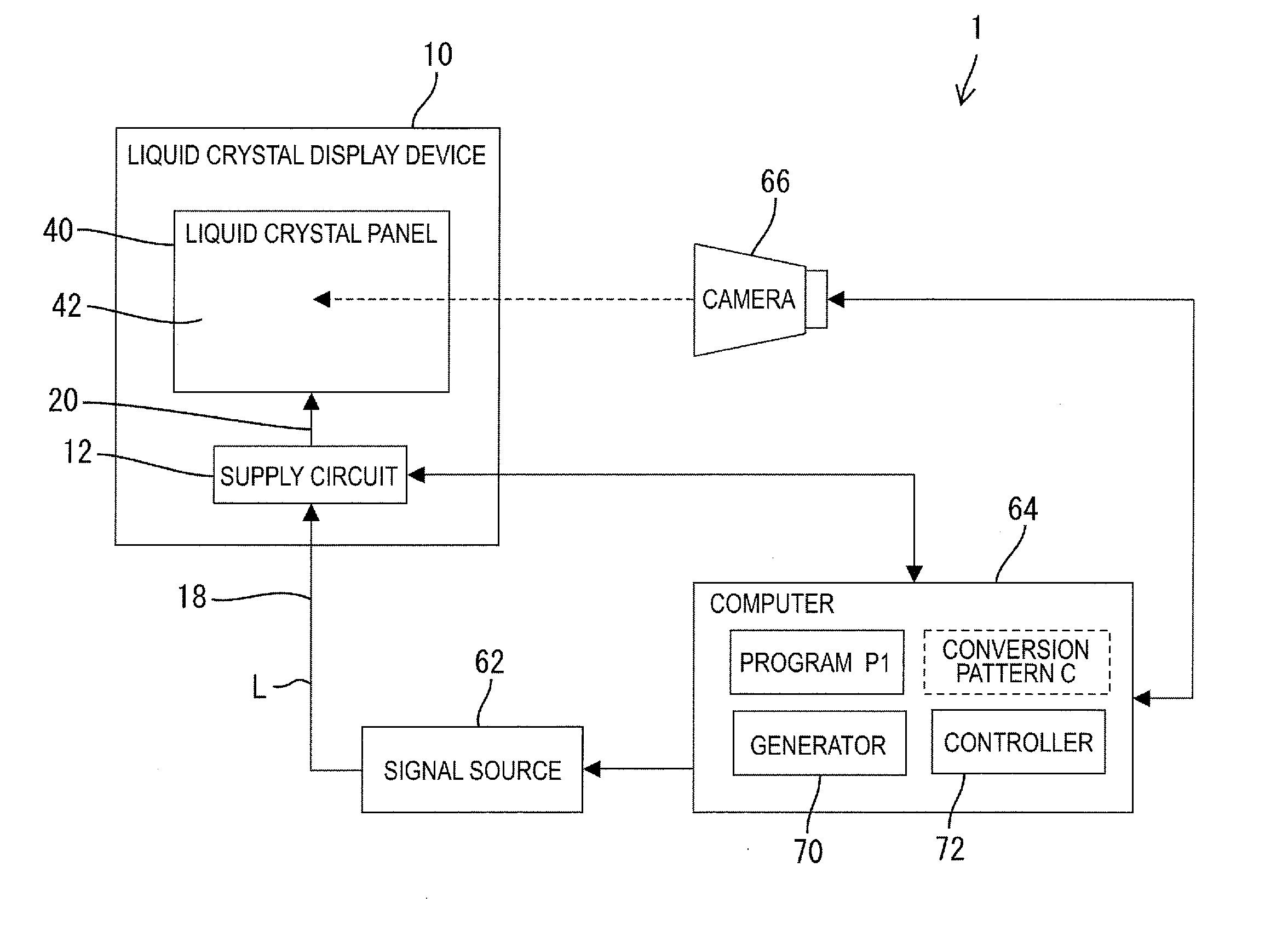
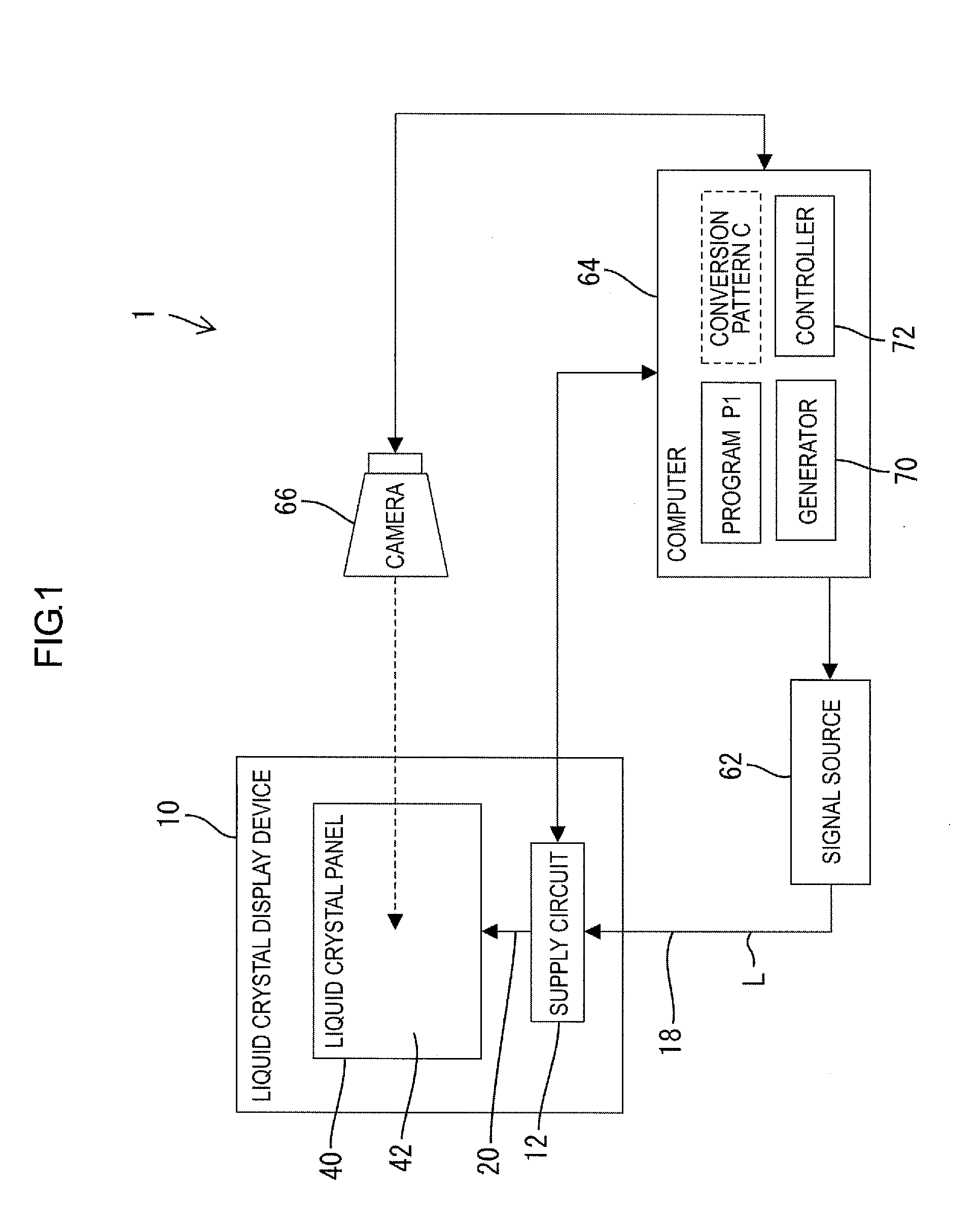
[0043]1. Configuration of Correction System
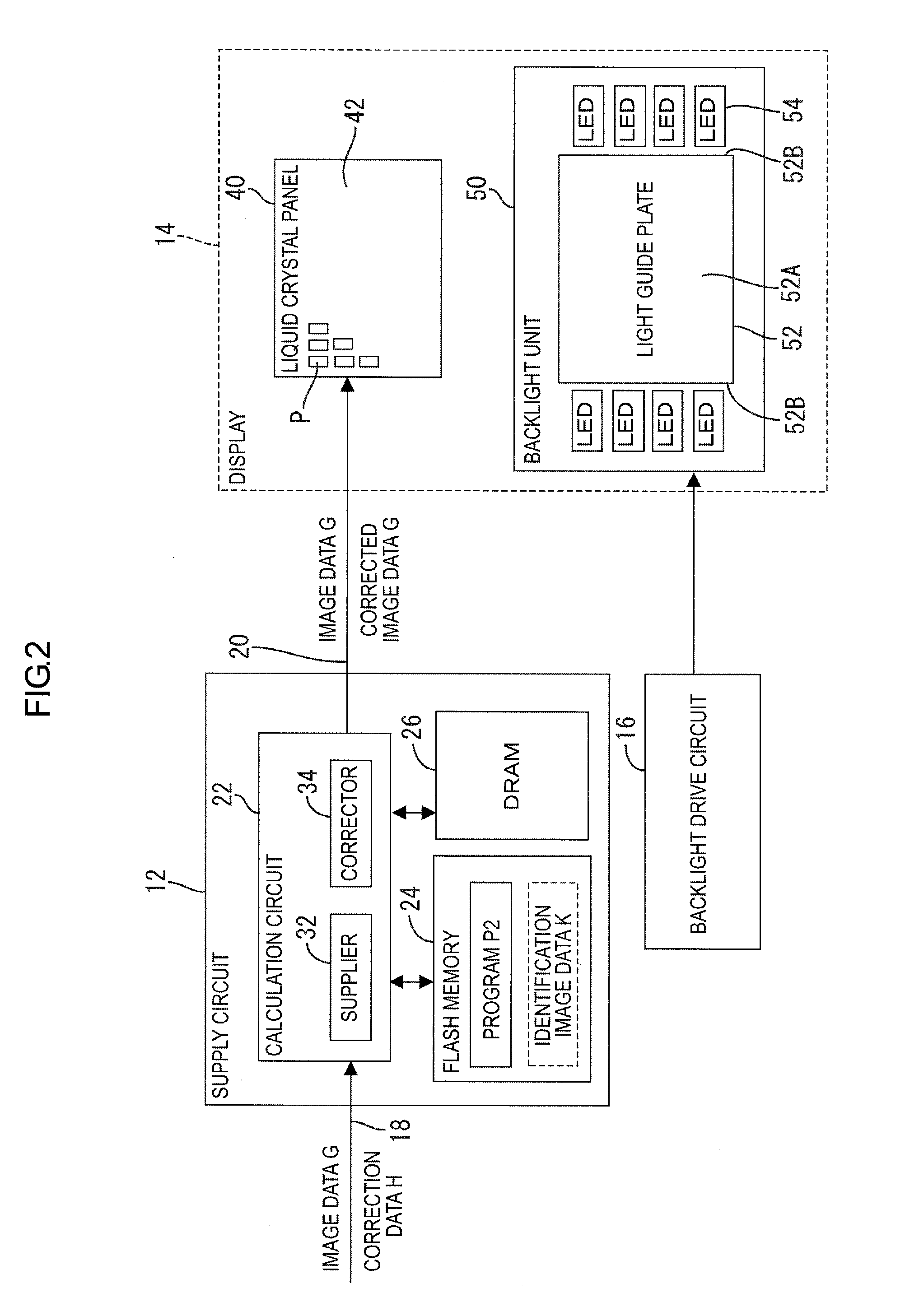
[0044]A configuration of a correction system 1 that corrects display unevenness of a liquid crystal display device 10 will be explained with reference to FIG. 1. As illustrated in FIG. 1, the system 1 includes the liquid crystal display device 10, a signal source 62, a computer 64 and a camera (one of examples of an image capturing device) 66. The liquid crystal display device 10 includes a supply circuit 12 and a liquid crystal panel (one of examples of a display panel) 40, as will be d...
second embodiment
[0086]A second embodiment will be explained with reference to FIG. 12. Unlike the first embodiment, in the correction system 1 of the present embodiment, the FLASH memory 24 of the supply circuit stores identification image data (one of examples of identification mark) K that informs occurrence of a transmission error between the computer 64 and the supply circuit 12. In the following explanation, the description same as that in the first embodiment will be omitted.
[0087]1. Process of Correction System
[0088]In the reading process, if receiving the correction data H1 at S62 and S66 that are set to be at different timing, the calculation circuit 22 compares the two correction data H1 (S70). If it is determined that the two correction data H1 is same (S70: Yes), as illustrated in FIG. 12, the calculation circuit 22 reads the identification image data K for displaying “◯” among the identification image data K stored in the FLASH memory 24. The identification image “◯” represents that th...
third embodiment
[0094]A third embodiment will be explained with reference to FIG. 13. Unlike the first embodiment, according to the correction system 1 of the present embodiment, as illustrated with a dotted line in FIG. 1, the computer 64 stores a plurality of conversion patterns C with which the correction data H1 input from the computer 64 to the supply circuit 12 is converted. In the following explanation, description same as that in the first embodiment will be omitted.
[0095]1. Process of Correction System
[0096]In the reading process, as illustrated in FIG. 13, the computer 64 converts the correction data H1 with a first conversion pattern C1 (S61) prior to input of the correction data H1 to the supply circuit 12 in S62, and inputs the converted correction data H1 to the supply circuit 12. Prior to the input of the correction data H1 to the supply circuit 12 at S66, the correction data H1 is converted with a second conversion pattern C2 that is different from the first conversion pattern C1 (S...
PUM
 Abstract
Description
Claims
Application Information
 - R&D
- Intellectual Property
- Life Sciences
- Materials
- Tech Scout
- Unparalleled Data Quality
- Higher Quality Content
- 60% Fewer Hallucinations
Browse by: Latest US Patents, China's latest patents, Technical Efficacy Thesaurus, Application Domain, Technology Topic, Popular Technical Reports.
© 2025 PatSnap. All rights reserved.Legal|Privacy policy|Modern Slavery Act Transparency Statement|Sitemap|About US| Contact US: help@patsnap.com