Image coding apparatus, method for coding image, program therefor, image decoding apparatus, method for decoding image, and program therefor

a technology of image coding and decoding apparatus, which is applied in the field of image coding apparatus, can solve the problems of large codes generated, inability to efficiently perform parallel processing on a subblock basis, and disable the improvement of coding and decoding processing speed

Active Publication Date: 2013-12-26
CANON KK
View PDF7 Cites 11 Cited by
  • Summary
  • Abstract
  • Description
  • Claims
  • Application Information

AI Technical Summary

Benefits of technology

[0009]The present invention is directed to enabling coding and decoding for each subblock to be performed in paral

Problems solved by technology

Therefore, it has not been possible to efficiently perform parallel processing on a subblock basis, disabling improvement in coding and decoding processing speed.
Acqu

Method used


Image

  • Image coding apparatus, method for coding image, program therefor, image decoding apparatus, method for decoding image, and program therefor
  • Image coding apparatus, method for coding image, program therefor, image decoding apparatus, method for decoding image, and program therefor
  • Image coding apparatus, method for coding image, program therefor, image decoding apparatus, method for decoding image, and program therefor

Examples


Embodiment Construction

[0037]Various exemplary embodiments, features, and aspects of the invention will be described in detail below with reference to the drawings.

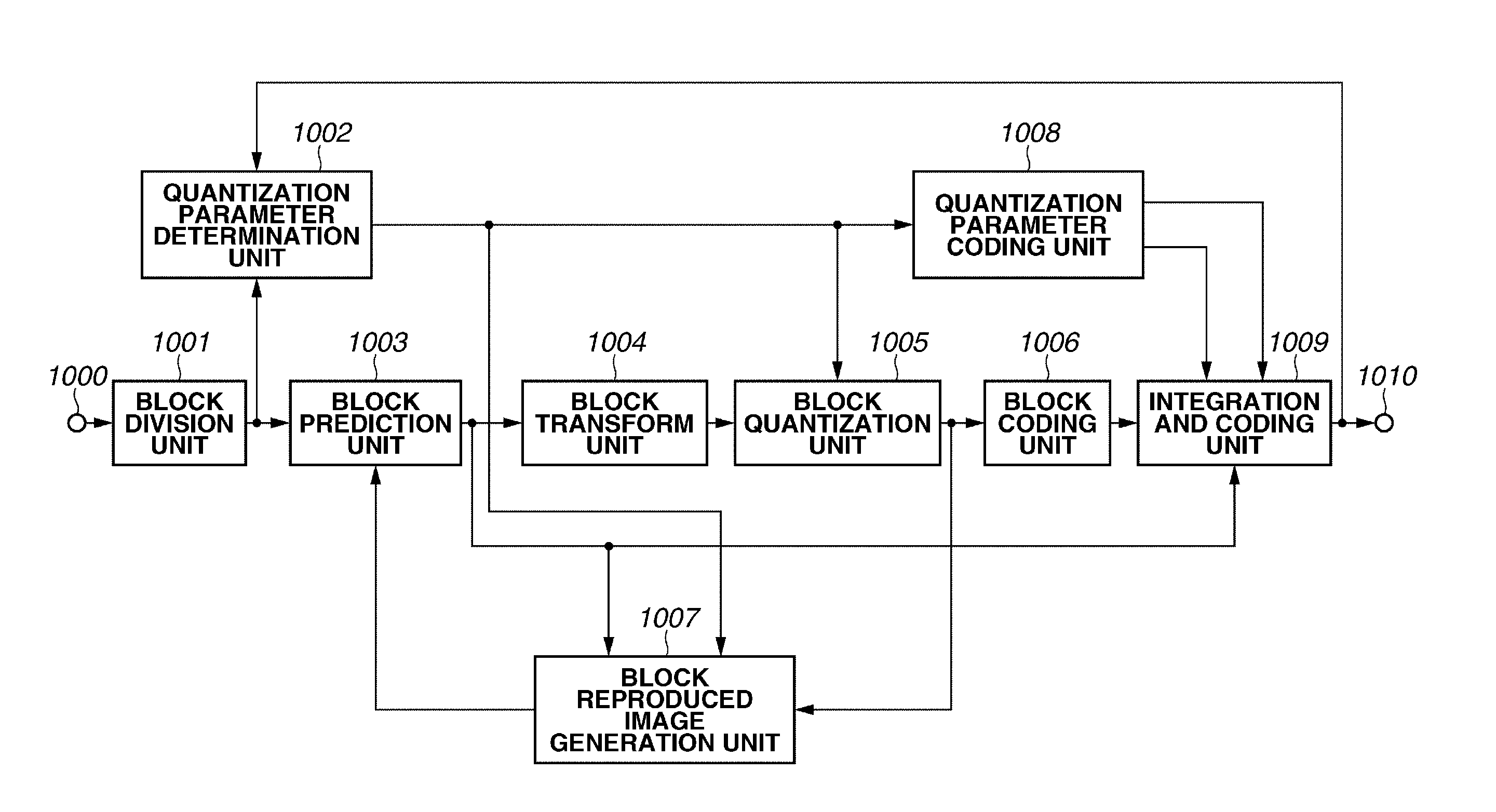
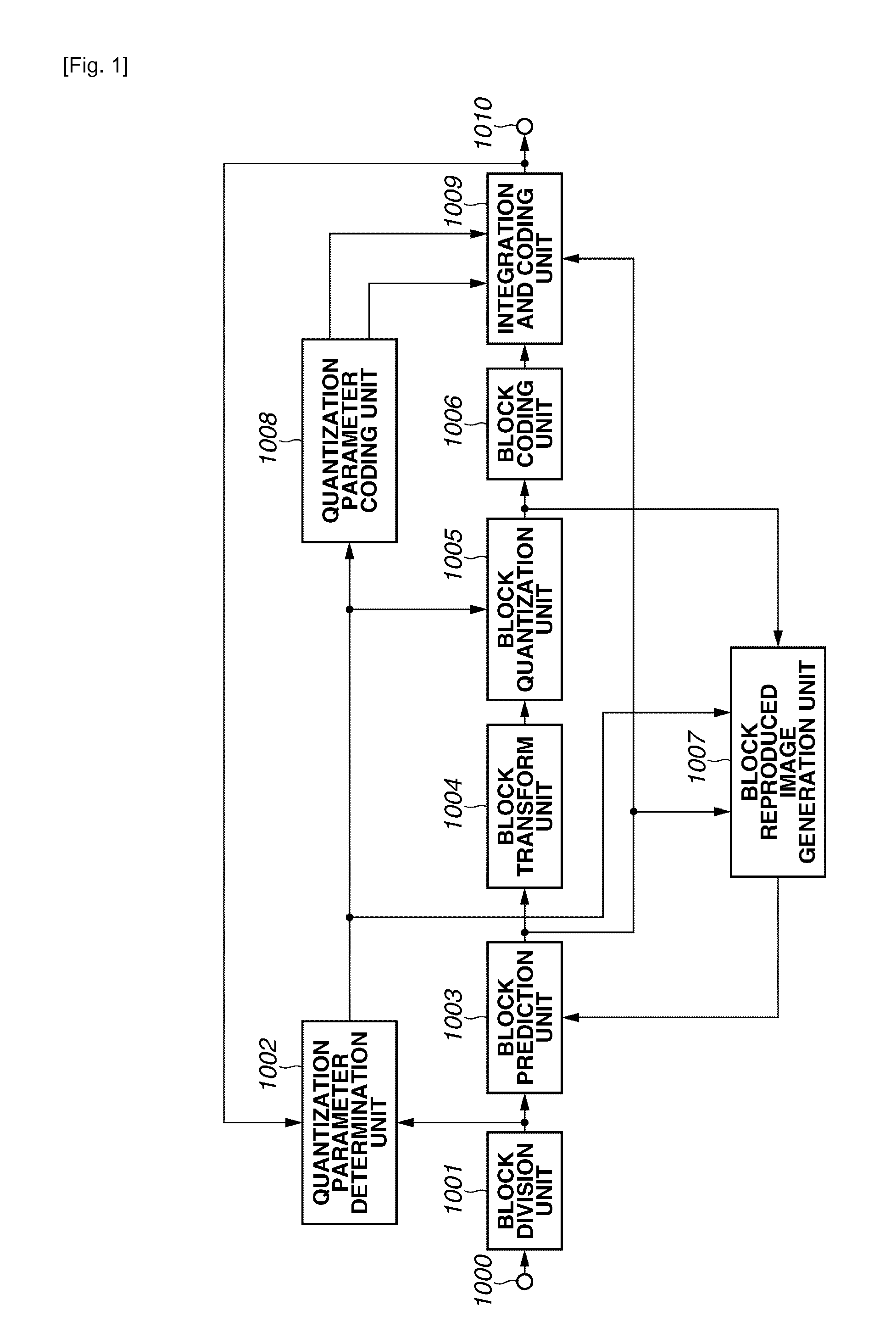
[0038]FIG. 1 is a block diagram illustrating an image coding apparatus according to a first exemplary embodiment of the present invention. Referring to FIG. 1, the image coding apparatus inputs image data from a terminal 1000.

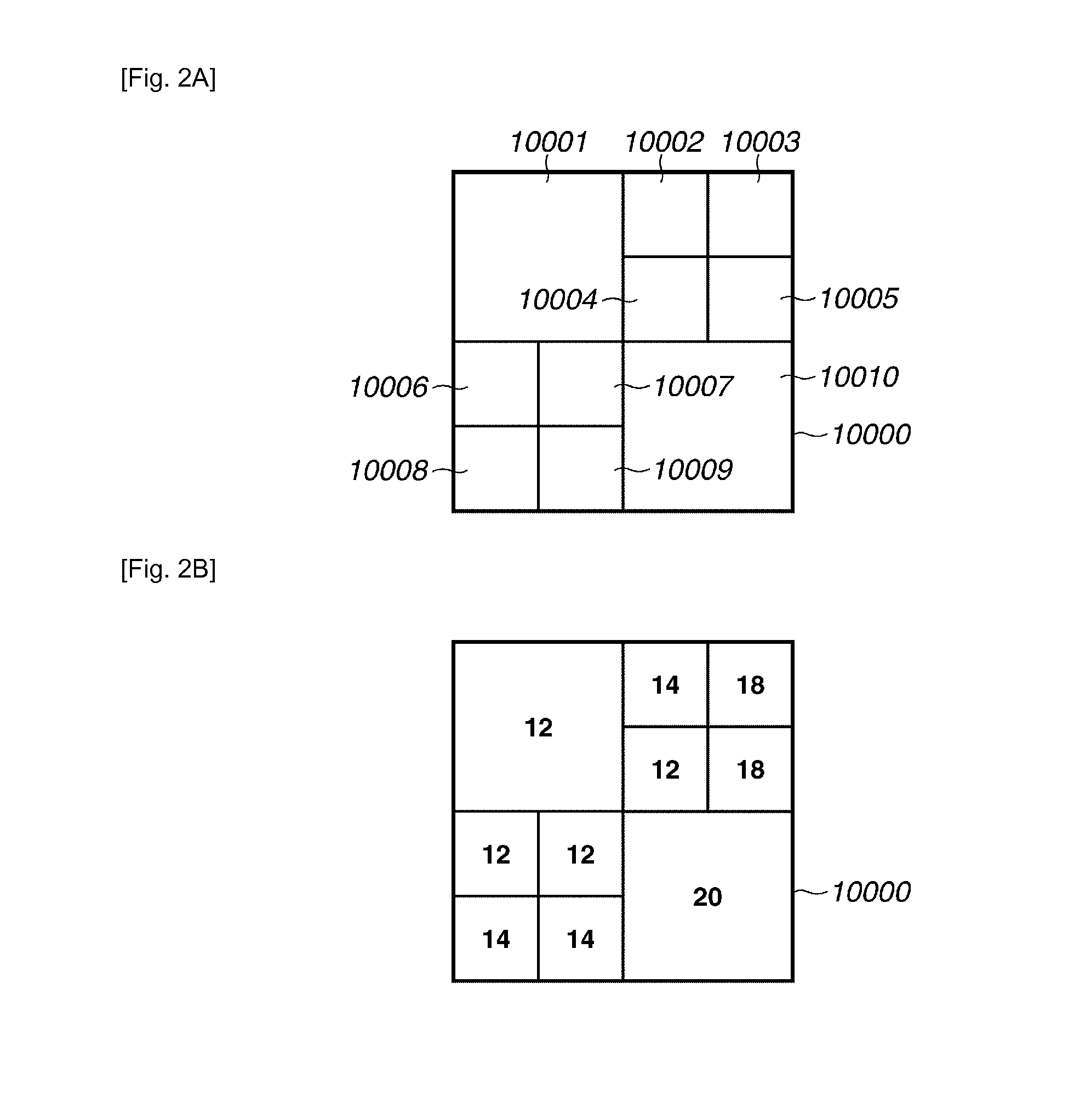
[0039]A block division unit 1001 divides the input image into a plurality of basic blocks, i.e., clips a basic block from the input image a plurality of number of times, and, if necessary, further divides each basic block into a plurality of subblocks. The image coding apparatus performs quantization control on a subblock basis. Although the input image is assumed to have 8-bit pixel values to simplify descriptions, the pixel value is not limited thereto. The size of a basic block is 64×64 pixels, and a minimum size of a subblock is 8×8 pixels. In this case, the basic block includes four subblocks. Although block division ...


PUM


Abstract

An image processing apparatus includes a division unit configured to divide an input image into a plurality of subblocks subjected to quantization control a subblock quantization parameter calculation unit configured to calculate a quantization parameter of each of the subblocks, a basic block quantization parameter calculation unit configured to set a basic block including at least two subblocks and to calculate a quantization parameter of the basic block, a difference value calculation unit configured to calculate a difference value between the quantization parameter of the basic block and the quantization parameter of each subblock included in the basic block, and a difference value coding unit configured to code the difference value.

Description

TECHNICAL FIELD [0001]The present invention relates to an image coding apparatus, a method for coding an image, a program therefor, an image decoding apparatus, a method for decoding an image, and a program therefor. More particularly, the present invention relates to a predictive coding method for quantization parameters in an image.BACKGROUND ART[0002]As a method for compressing and recording a moving image, the H.264 / MPEG-4AVC (hereafter referred to as H.264) is known (ISO / IEC 14496-10;2004 Information technology—Coding of audio-visual objects—Part 10: Advanced Video Coding). The H.264 is widely used for one-segment terrestrial digital broadcasting.[0003]The H.264 enables changing quantization parameters in macroblock units (16×16 pixels) by using the mb_qp_delta code. A formula 7-23 discussed in the above-mentioned document adds a difference value mb_qp_delta to a quantization parameter QPYPREV of a macroblock last decoded to change quantization parameters in macroblock units (1...

Claims


Application Information

Patent Timeline
IPC IPC(8): H04N7/32H04N19/00H04N19/119H04N19/126H04N19/136H04N19/14H04N19/176H04N19/423H04N19/46H04N19/463H04N19/503H04N19/593H04N19/60H04N19/61H04N19/625H04N19/70H04N19/91H04N19/96
CPCH04N19/00569H04N19/124H04N19/167H04N19/176H04N19/436H04N19/463H04N19/50H04N19/61H04N19/91H04N19/44H04N19/00
Inventor MAEDA, MITSURU
Owner CANON KK
Why Eureka
Try Eureka