Supercharge Your Innovation With Domain-Expert AI Agents!

Impeller of Cooling Fan

a technology of cooling fan and impeller, which is applied in the direction of machines/engines, stators, liquid fuel engines, etc., can solve the problems of large amount of metal needed, large manufacturing cost of this impeller, and large manufacturing process of the impeller

Inactive Publication Date: 2013-12-26
SUNONWEALTH ELECTRIC MACHINE IND
View PDF7 Cites 2 Cited by
  • Summary
  • Abstract
  • Description
  • Claims
  • Application Information

AI Technical Summary

Benefits of technology

The patent aims to create an impeller with a metal base that is small in size, allowing for a cooling fan to be used in small electrical devices. The technical effect is to provide a compact and efficient solution for cooling in miniaturized devices.

Problems solved by technology

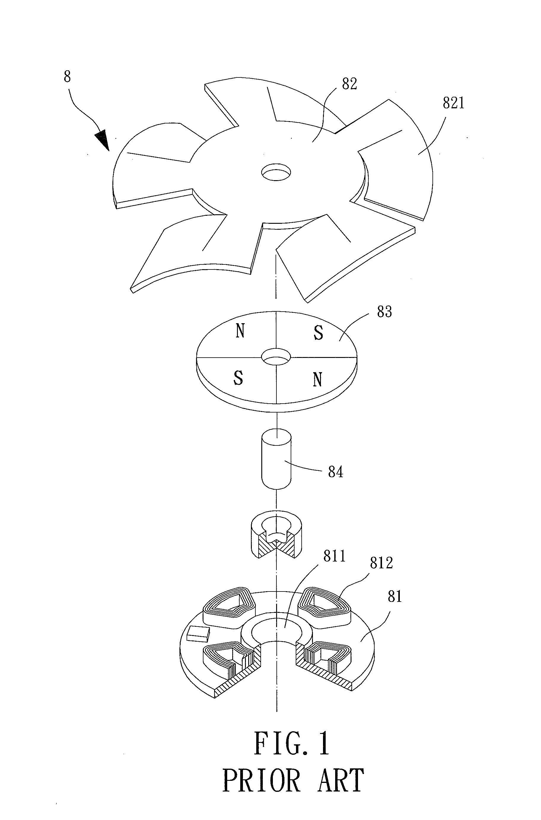
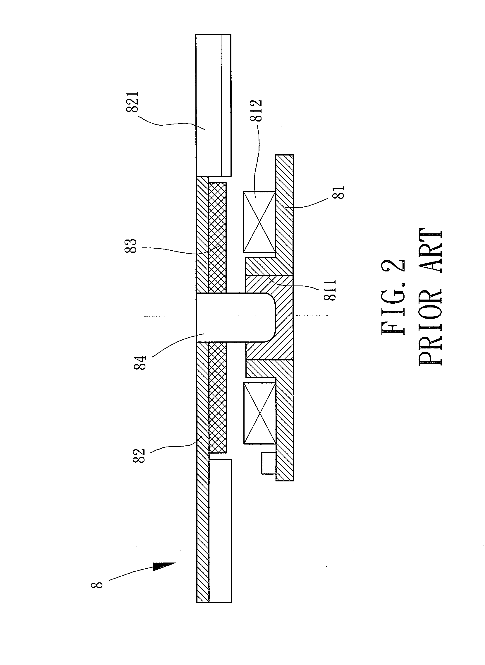
Although the impeller 82 made of the metal plate is thin, the manufacturing process of the impeller 82 is complex and a large amount of metal is needed, such that manufacturing cost of this impeller 82 is large.
Furthermore, the metal impeller 82 is much heavier than others made of plastic, and this may result in high loading in weight and further affect rotational performance.
Therefore, due to the metal housing 91 having an increased thickness, the rotor 9 inside an electrical device may become a stumbling block of axial miniaturization of the electrical device.

Method used


Image

  • Impeller of Cooling Fan
  • Impeller of Cooling Fan
  • Impeller of Cooling Fan

Examples


Embodiment Construction

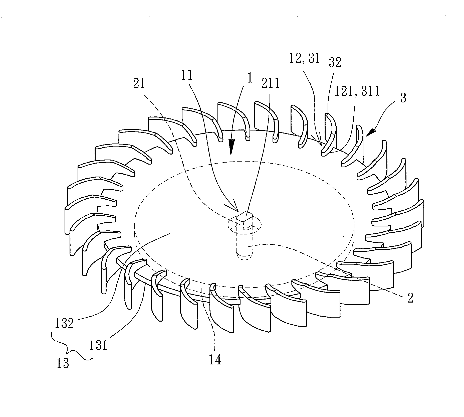
[0043]Referring to FIGS. 4, 5 and 6, a first embodiment of an impeller of a cooling fan is shown, which includes a metal base 1, a shaft 2 coupled with a central part of the metal base 1, and a plurality of plastic blades 3 coupled with a periphery of the metal base 1.

[0044]The metal base 1 has a shaft-coupling portion 11 and a first assembling portion 12. The shaft-coupling portion 11 is formed in the central part of the metal base 1 and is a means for coupling with the shaft 2. In this embodiment, the shaft-coupling portion 11 is a hole for partially receiving the shaft 2. The first assembling portion 12 is apart from the shaft-coupling portion 11 and is a means for the plurality of plastic blades 3 to couple with the metal base 1, wherein the first assembling portion 12 can be selected from various structures for the injection-formed plastic blades 3 to mount on, which is discussed in detail later. The metal base 1 further includes a flat portion 13 having no axial curve and betw...


PUM


Abstract

An impeller of a cooling fan includes a metal base, a shaft and a plurality of plastic blades. The metal base includes a shaft-coupling portion, a first assembling portion apart from the shaft-coupling portion, and a flat portion between the shaft-coupling portion and the first assembling portion, wherein the flat portion oppositely has a first flat surface and a second flat surface, and a permanent magnet is mounted on the first flat surface. The shaft has a fixing end coupled with the shaft-coupling portion of the metal base. Each of the plastic blades has a second assembling portion coupled with the first assembling portion of the metal base.

Description

BACKGROUND OF THE INVENTION[0001]1. Field of the Invention[0002]The present invention generally relates to an impeller of cooling fan and, more particularly, to an impeller suitable for thin cooling fan.[0003]2. Description of the Related Art[0004]In the current trend of miniaturization for electrical devices, cooling fans disposed inside miniaturized electrical devices to drive air currents for cooling have to be smaller than conventional fans. In this condition, the size of an impeller in a cooling fan becomes a critical feature of whether the cooling fan is suitable to be applied in a miniaturized electrical device.[0005]Referring to FIGS. 1 and 2, an invention of Taiwan Patent No. 1293106, entitled as “Thin-Type Fan,” is shown. The invention is about a conventional cooling fan 8 including a base 81, an impeller 82, a magnetic plate 83 and a shaft 84. The base 81 has a central hole 811 and a coil unit 812. The impeller 82 has a plurality of bent blades 821. The magnetic plate 83 ...

Claims


Application Information

Patent Timeline
Patent Type & Authority Applications(United States)
IPC IPC(8): F01D5/28
CPCF01D5/28F04D25/064F04D29/281F04D29/325
Inventor HORNG, ALEX
Owner SUNONWEALTH ELECTRIC MACHINE IND
Features
  • R&D
  • Intellectual Property
  • Life Sciences
  • Materials
  • Tech Scout
  • Unparalleled Data Quality
  • Higher Quality Content
  • 60% Fewer Hallucinations
Learn More