Lithography apparatus, and method of manufacture of product

a technology of lithography and product, applied in the direction of photomechanical equipment, instruments, heat measurement, etc., can solve the problem of greatly reduced throughput and achieve the effect of improving throughpu

Inactive Publication Date: 2013-12-26
CANON KK
View PDF2 Cites 5 Cited by
  • Summary
  • Abstract
  • Description
  • Claims
  • Application Information

AI Technical Summary

Benefits of technology

[0006]The present invention provides, for example, a lithography apparatus that compensates for a defective charged particle beam and has advantage of throughput.

Problems solved by technology

However, there is a possibility that the throughput is greatly reduced when the writing method disclosed in Published Japanese Translation No. 2009-503844 is performed.

Method used


Image

  • Lithography apparatus, and method of manufacture of product
  • Lithography apparatus, and method of manufacture of product
  • Lithography apparatus, and method of manufacture of product

Examples


first embodiment

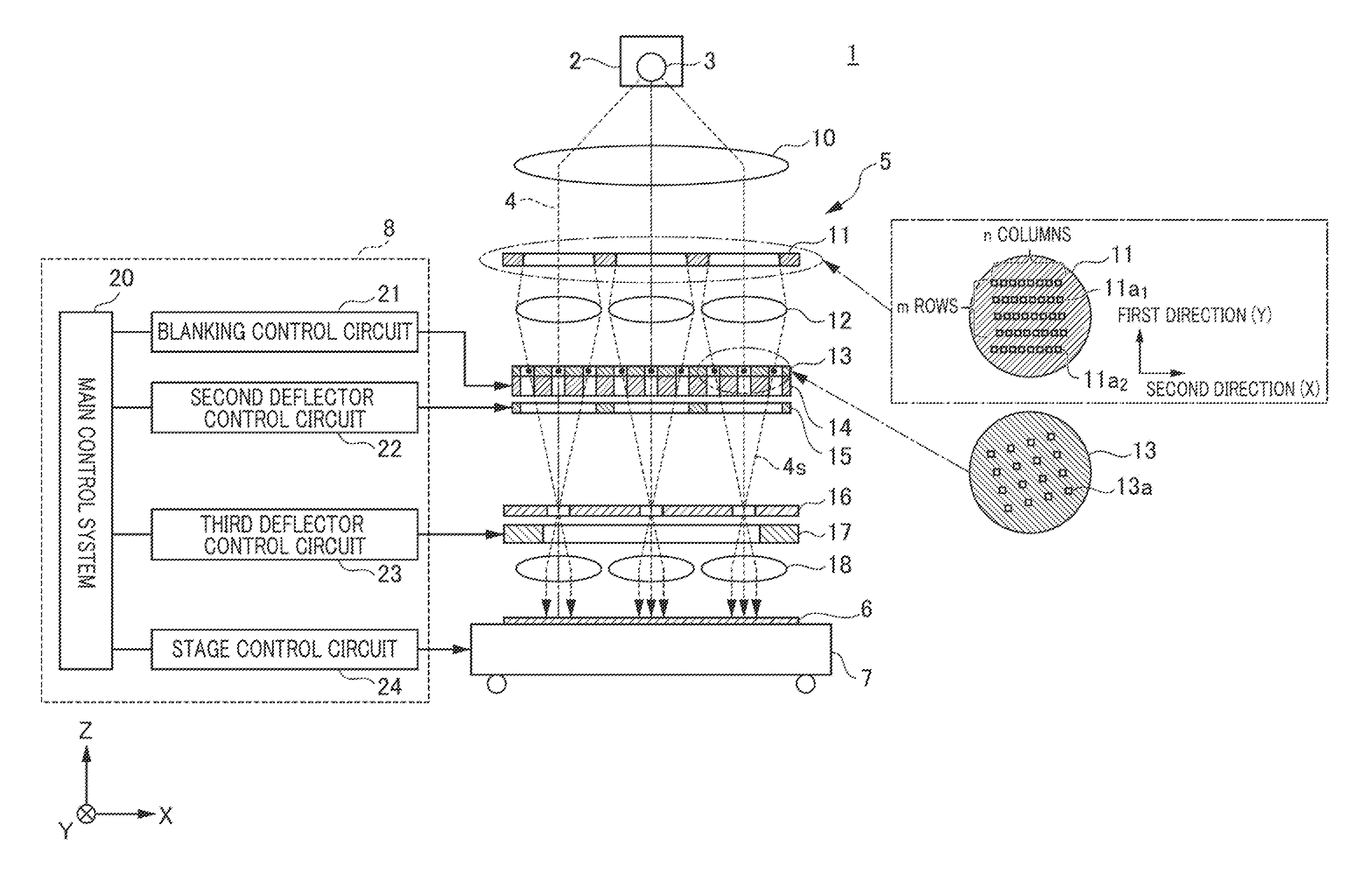
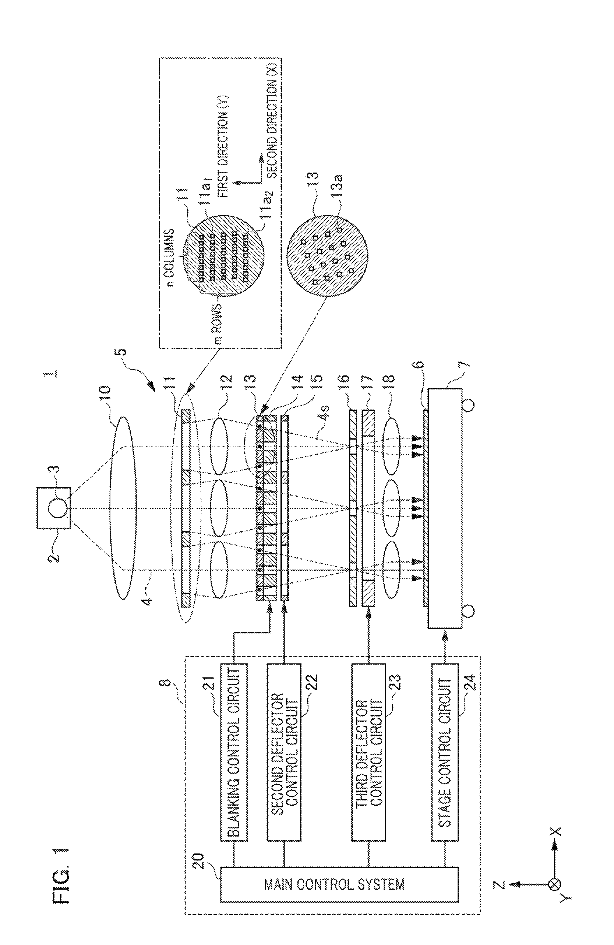
[0021]Firstly, a lithography apparatus according to a first embodiment of the present disclosure will be described. The lithography apparatus that is described in the embodiment is configured as a multibeam lithography apparatus that writes a predetermined pattern onto a predetermined position of a substrate by deflecting a plurality of charged particle beams and executing separate control of the blanking (irradiation OFF position) of the charged particle beam. As used herein, charged particle beam means an electron beam or ion beam. FIG, 1 is a schematic view of the configuration of the lithography apparatus 1 according to the present embodiment. In FIG. 1, a Z axis is configured in a nominal irradiation direction of a charged particle beam relative to the substrate, and the X axis and Y axis are orthogonally disposed in a plane that is perpendicular to the Z axis. The first direction and the second direction as used in the following description are mutually orthogonal and parallel...

second embodiment

[0046]Next, a lithography apparatus according to the second embodiment of the present disclosure will be described, FIG. 11 is a schematic plan view illustrating a configuration of a lithography apparatus 70 according to the present embodiment. FIG. 11 denotes the same elements of configuration as the lithography apparatus 1 according to the first embodiment with the same reference numerals, and the description will not be repeated. The characteristic feature of the lithography apparatus 70 resides in the point that while the optical system 5 includes a deflector array corresponding to the second deflector array 15 that is present in the lithography apparatus 1 according to the first embodiment, the third deflector array 17 has been omitted. In the lithography apparatus 70, the operation of deflecting and scanning of each sub-beam 4s in the first direction and the second direction in order to draw the figure along the second direction, that is originally executed by the third deflec...


PUM


Abstract

A lithography apparatus writes with a charged particle beam on a substrate scanned in a first direction. The apparatus includes a shielding device which individually shields a plurality of charged particle beams in first and second charged particle beam groups, a holder for the substrate movable in the first direction, and a controller. If a defective beam that does not satisfy a condition exists in the first charged particle beam group, the controller is configured to cause the shielding device to shield the defective beam and to transmit a compensating beam, of the second charged particle beam group, for compensating for the defective beam, and to control writing with the compensating beam based on relative positions, in the first direction, between the compensating beam and a charged particle beam to be compensated for by the compensating beam.

Description

BACKGROUND OF THE INVENTION[0001]1. Field of the Invention[0002]The present disclosure relates to a lithography apparatus that performs writing on a substrate with a plurality of charged particle beams, and to a method of manufacturing an article.[0003]2. Description of the Related Art[0004]A lithography apparatus that executes writing on a substrate by controlling the blanking, and deflecting and scanning with a charged particle beam such as an electron beam is known. This lithography apparatus is employed as a pattern formation technique in substitution for an optical exposure method in the product or the like of a 4 GDRAM and higher memory device having a line width of no more, than 0.1 micrometers An example of this lithography apparatus is a multibeam lithography apparatus that executes writing using a plurality of charged particle beams to meet a request for higher throughput. In relation to the above type of multibeam lithography apparatus, PCT Laid Open Application 2009 / 1472...

Claims


Application Information

Patent Timeline
Patent Type & Authority Applications(United States)
IPC IPC(8): H01J37/317
CPCH01J37/3174H01J37/304H01J37/3177H01J2237/31766B82Y10/00B82Y40/00
Inventor KAWAMOTO, TAKAYUKISANO, KENTARO
Owner CANON KK
Why Eureka
Try Eureka