Eureka AIR delivers breakthrough ideas for toughest innovation challenges, trusted by R&D personnel around the world.

Methods and systems for enhancing ultrasonic visibility of energy-delivery devices within tissue

a technology of energy-delivery devices and ultrasonic visibility, which is applied in the field of electrosurgical devices, can solve the problems of vibration of the weight at the distal end difficult to visualize the ablation probe, needle, catheter, etc. within the body using ultrasonography, etc., and achieve the effect of enhancing the ultrasonic visibility of the energy-delivery devi

Active Publication Date: 2013-12-26
TYCO HEALTHCARE GRP LP
View PDF3 Cites 26 Cited by
  • Summary
  • Abstract
  • Description
  • Claims
  • Application Information

AI Technical Summary

Benefits of technology

This patent describes a method for improving the visibility of a surgical instrument during ultrasonography, which can help with positioning and guiding the instrument during a procedure. This is done by using a hydraulic assembly and a flow-control device to control the movement of fluid around the instrument. The method can be applied to different types of surgical instruments, such as electrodes, probes, or antennas. The ultimate goal is to make the procedure safer and more efficient by improving the visibility of the surgical instrument and allowing better guidance during the procedure.

Problems solved by technology

However, during certain surgical procedures, it can be difficult to visualize an ablation probe, needle, catheter, etc. within the body using ultrasonography.
As a result, it is difficult to guide surgical instruments to a proper location and / or position within the body, such as, for example, an ablation probe within a tissue mass to be ablated.
During placement of the energy-delivery device within tissue or at anytime when enhanced ultrasonic visibility of the energy-delivery device within tissue is desired, the motor is actuated thereby causing vibration of the weight at the distal end of the energy-delivery device.
The vibration of the weight causes the energy-delivery device to vibrate.
This causes high pressure pulses in the fluid flow.
At higher pumping speeds, the fluid pressure of the circulating cooling fluid through the energy-delivery device is increased, thereby causing increased vibration of the energy-delivery device.

Method used


Image

  • Methods and systems for enhancing ultrasonic visibility of energy-delivery devices within tissue
  • Methods and systems for enhancing ultrasonic visibility of energy-delivery devices within tissue
  • Methods and systems for enhancing ultrasonic visibility of energy-delivery devices within tissue

Examples


Embodiment Construction

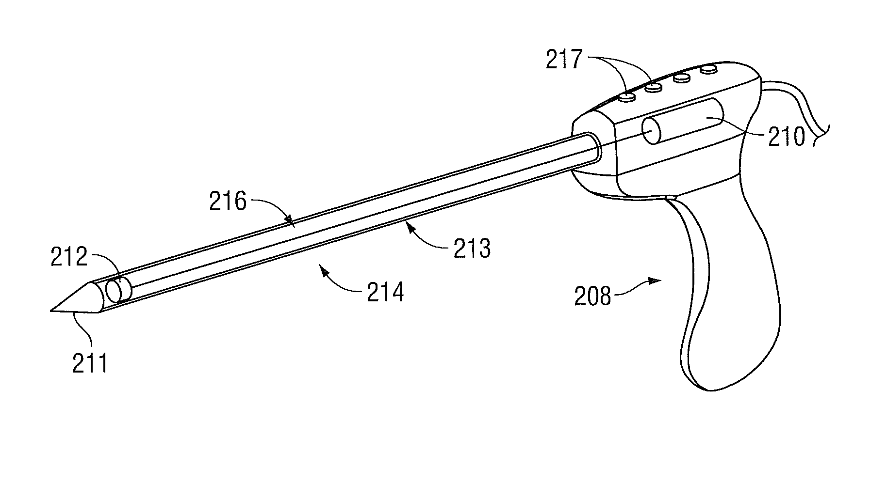
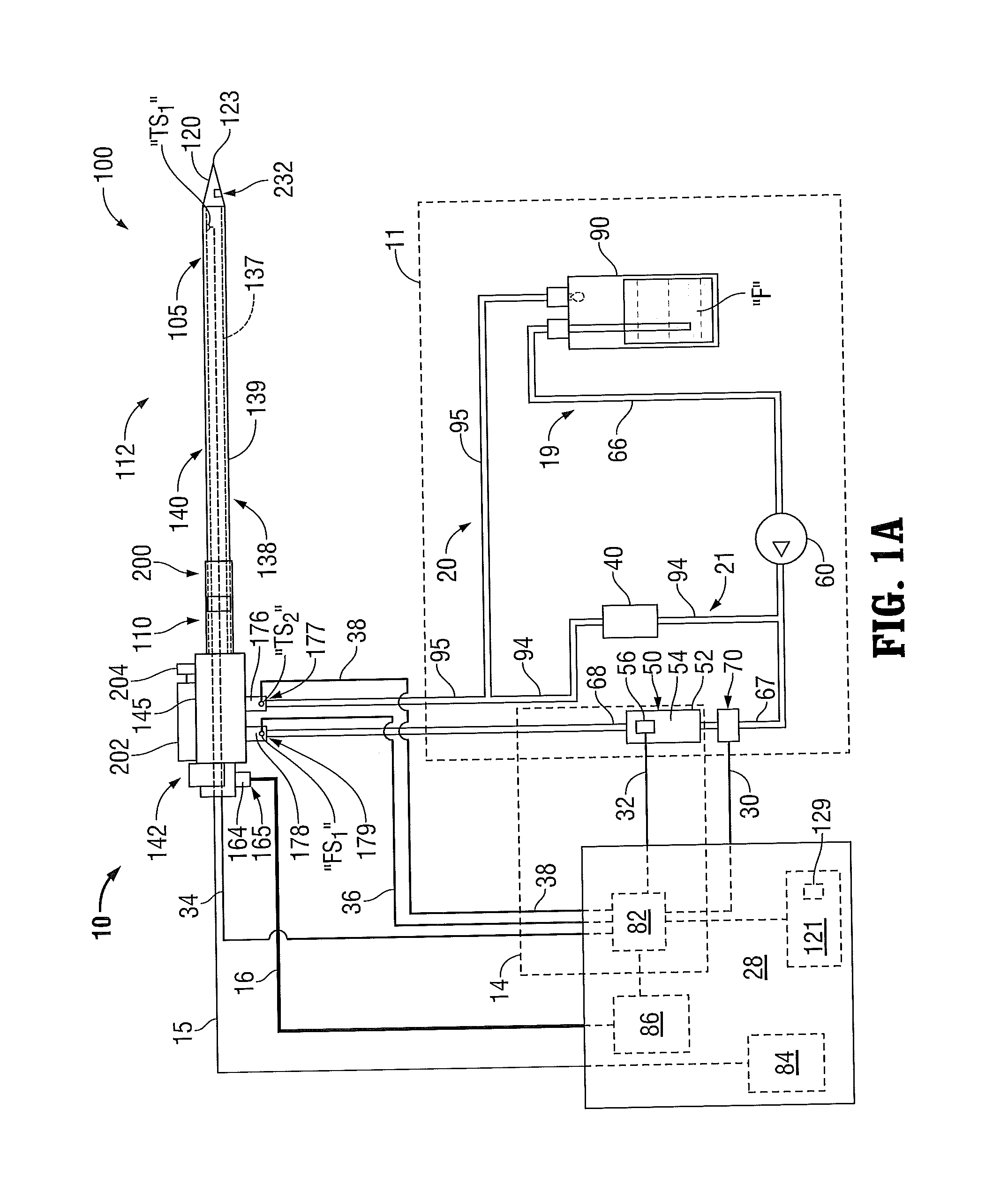
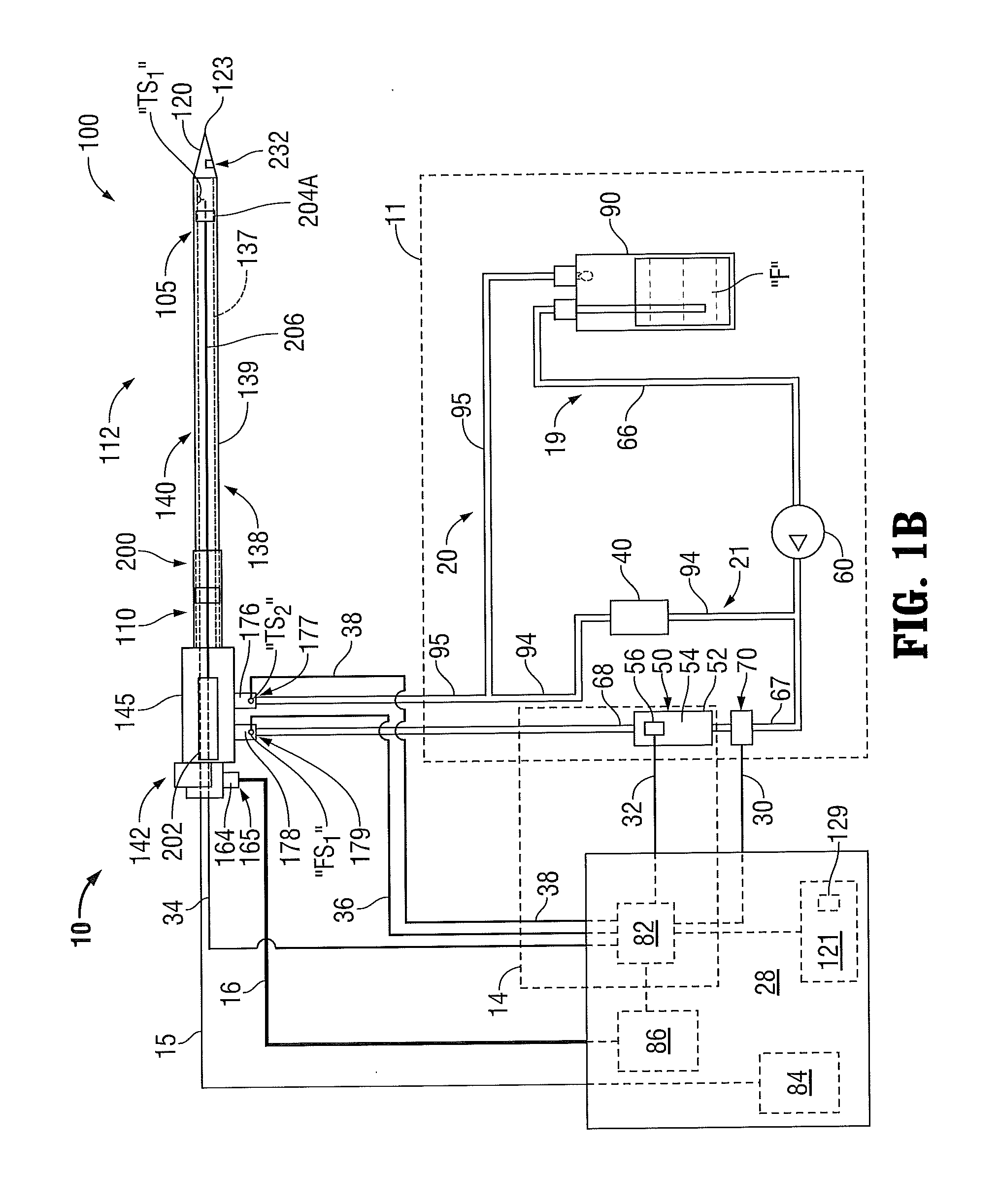
[0065]Hereinafter, embodiments of the presently-disclosed methods and systems for enhancing ultrasonic visibility of energy-delivery devices (or other component) of an electrosurgical system within tissue are described with reference to the accompanying drawings. Like reference numerals may refer to similar or identical elements throughout the description of the figures.

[0066]This description may use the phrases “in an embodiment,”“in embodiments,”“in some embodiments,” or “in other embodiments,” which may each refer to one or more of the same or different embodiments in accordance with the present disclosure. For the purposes of this description, a phrase in the form “NB” means A or B. For the purposes of the description, a phrase in the form “A and / or B” means “(A), (B), or (A and B)”. For the purposes of this description, a phrase in the form “at least one of A, B, or C” means “(A), (B), (C), (A and B), (A and C), (B and C), or (A, B and C)”.

[0067]In accordance with the present d...


PUM


Abstract

In accordance with aspects of the present disclosure, electrosurgical systems are provided generally including at least one energy-delivery device for delivering energy to tissue when inserted or embedded within tissue. The energy-delivery device can be a tissue ablation device, such as an ablation probe, needle, etc. for ablating tissue as commonly known in the art. The electrosurgical systems include at least one structure and / or operational characteristic for enhancing ultrasonic visibility of the energy-delivery devices within tissue during ultrasonography.

Description

CROSS REFERENCE TO RELATED APPLICATION[0001]The present application claims the benefit of and priority to U.S. Provisional Application Ser. No. 61 / 664,559, filed on Jun. 26, 2012, the entire contents of which are incorporated herein by reference.BACKGROUND[0002]1. Technical Field[0003]The present disclosure relates to electrosurgical devices suitable for tissue ablation applications and, more particularly, to methods and systems for enhancing ultrasonic visibility of energy-delivery devices within tissue.[0004]2. Discussion of Related Art[0005]Treatment of certain diseases requires the destruction of malignant tissue growths, e.g., tumors. Electromagnetic radiation can be used to heat and destroy tumor cells. Treatment may involve inserting ablation probes into tissues where cancerous tumors have been identified. Once the probes are positioned, electromagnetic energy is passed through the probes into surrounding tissue.[0006]In the treatment of diseases such as cancer, certain types...

Claims


Application Information

Patent Timeline
IPC IPC(8): A61B8/08A61B18/14
CPCA61B8/0841A61B18/1482A61B8/481A61B18/1477A61B2018/00023A61B2018/00285A61B18/1815A61B2018/00577A61B2018/00642A61B2018/00666A61B2018/00684A61B2018/00744A61B2018/00797A61B2017/00539A61B2018/1425A61B2090/378A61B90/39A61B2090/3929
Inventor ARTS, GENE H.PETERSON, DARION R.BRANNAN, JOSEPH D.VANTUNO, JOHN R.LARSON, ERIC W.
Owner TYCO HEALTHCARE GRP LP
Why Eureka
Eureka Blog
Learn More