Cooling system and cooling method

a cooling system and cooling technology, applied in the field of cooling system and cooling method, can solve the problems of increasing the possibility of system stop, consuming air-conditioning power of the cooling system, etc., and achieve the effect of efficient air-conditioning

Inactive Publication Date: 2014-01-02
HITACHI LTD
View PDF13 Cites 46 Cited by
  • Summary
  • Abstract
  • Description
  • Claims
  • Application Information

AI Technical Summary

Benefits of technology

[0016]According to the present invention, air conditioning can be efficiently performed.

Problems solved by technology

Incidentally, when electronic devices are placed in a high-temperature environment, the possibility of occurrence of a trouble such as a system stop increases.
According to the techniques disclosed in Patent Literatures 1 and 2, although the cooling can be assisted by arranging a cooling system around the electronic device, the cooling system consumes air-conditioning power.

Method used


Image

  • Cooling system and cooling method
  • Cooling system and cooling method
  • Cooling system and cooling method

Examples


first embodiment

1. First Embodiment

1.1 Configuration of Cooling System

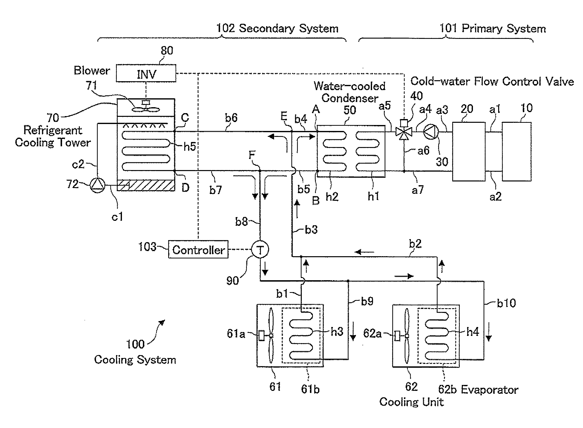
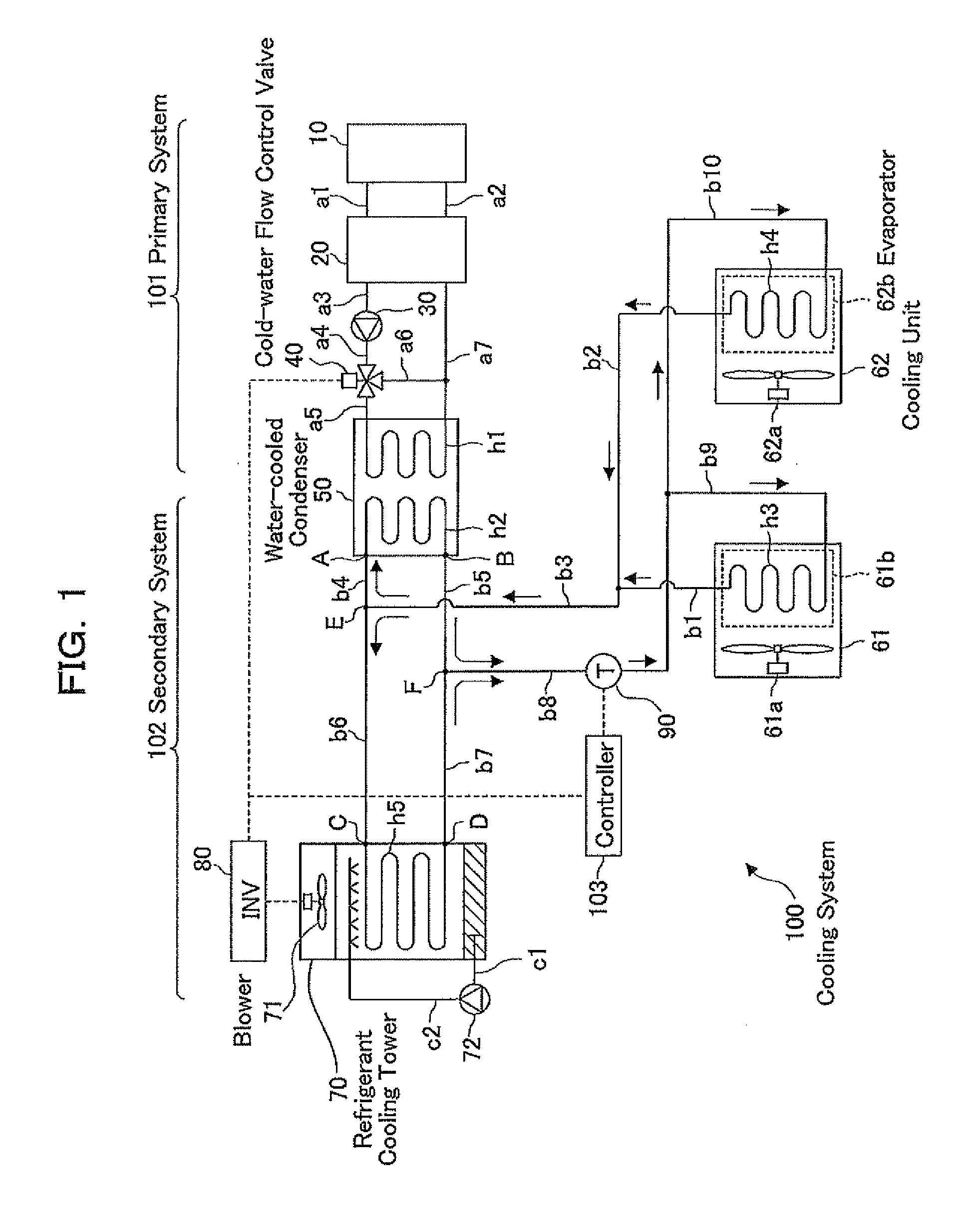
[0023]FIG. 1 is a diagram illustrating configuration of a cooling system for controlling the cold generation apparatus according to the first embodiment. As illustrated in FIG. 1, the cooling system 100 includes a primary system 101, a secondary system 102, and a controller 103.

1.2 Primary System

[0024]The primary system 101 includes heat-source equipment 10, a cool reservoir 20, a cold-water pump 30, a cold-water flow control valve 40, and a primary heat-transfer tube h1 in a water-cooled condenser 50.

[0025]The heat-source equipment 10 is, for example, a turbo refrigerator, and supplies cold to the cool reservoir 20. In the heat-source equipment 10, a compressor (not shown), a condenser (not shown), an expansion valve (not shown), and an evaporator (not shown) are connected in this order through piping arrangements, and a refrigerant is circulated in a known refrigeration cycle. In addition, the water flowing from the cool reserv...

second embodiment

2. Second Embodiment

2.1 Outline of Second Embodiment

[0083]The second embodiment is similar to the first embodiment except that an outside-air temperature sensor (not shown) and an outside-air humidity sensor (not shown) are arranged, and the operations of the controller 103 in the second embodiment are different from the first embodiment. Therefore, the following explanations are focused on the differences from the first embodiment, and the explanations on the portions of the second embodiment similar to the first embodiment are not presented below.

[0084]The outside-air temperature sensor (which is a means for detecting the temperature of the outside air) is placed in an arbitrary place in which the temperature of the outside air in the vicinity of the refrigerant cooling tower 70 can be detected, and outputs the detected temperature of the outside air to the controller 103 from time to time. The outside-air humidity sensor (which is a means for detecting the humidity of the outside...

third embodiment

3. Third Embodiment

3.1 Outline of Third Embodiment

[0098]The third embodiment is similar to the first embodiment except that the water-cooled condenser 50 and the refrigerant cooling tower 70 are connected in series. Therefore, the following explanations are focused on the differences from the first embodiment, and the explanations on the portions of the third embodiment similar to the first embodiment are not presented below.

3.2 Configuration of Third Embodiment FIG. 4 is a diagram illustrating a configuration of the cooling system 100A according to the third embodiment. In the primary system 101 in the configuration of FIG. 4 is similar to the primary system 101 in FIG. 1. In addition, the constructions of the water-cooled condenser 50, the cooling units 61 and 62, and the refrigerant cooling tower 70 in the configuration of FIG. 4 are similar to FIG. 1. Therefore, explanations on the constructions of the above elements are not repeated, and the following explanations are focused o...


PUM


Abstract

A cooling system includes; an evaporator evaporating a refrigerant by heat exchange with room air; a water-cooled condenser being arranged above the evaporator and condensing the refrigerant by heat exchange with cold water; a cold-water flow control valve controlling the flow rate of the cold water supplied to the water-cooled condenser; a refrigerant cooling tower being arranged above the evaporator and condensing the refrigerant by heat exchange with outside air; a blower being arranged at the refrigerant cooling tower and blowing the outside air; a refrigerant-temperature detector detecting the temperature of the refrigerant condensed by the water-cooled condenser and / or the refrigerant cooling tower; and a controller changing at least one of the opening in the cold-water flow control valve and the rotational speed of a motor in the blower according to the temperature.

Description

CROSS-REFERENCE TO RELATED APPLICATIONS[0001]This application claims the foreign priority benefit under 35 U.S.C. §119 of Japanese Patent Application No. 2012-145922, filed on Jun. 28, 2012, the disclosure of which is incorporated herein by reference.BACKGROUND OF THE INVENTION[0002]1. Field of the Invention[0003]The present invention relates to a cooling system and a cooling method.[0004]2. Description of the Related Art[0005]Recently, with the improvement in the information processing technology and the development of the Internet environment, required amounts of information processing have been increasing, and the business of the data processing center for massive processing of various types of information has been in the spotlight. For example, in the sever room in the data processing center, a great number of electronic devices are arranged in a centralized manner, and are continuously operating day and night.[0006]By the way, the rack mounted system is currently the mainstream...

Claims


Application Information

Patent Timeline
Patent Type & Authority Applications(United States)
IPC IPC(8): F25B39/02F24F11/76
CPCF25B39/02F25B23/006F25B25/005F25B2500/01F25B2700/02F25B2700/2106F24F2005/0025H05K7/2079H05K7/20836F24F2140/20F24F11/83F24F11/84F24F11/76F24F2110/00F24F11/30F24F3/065F25B23/00F25B25/00H05K7/202H05K7/20609
Inventor ITO, JUNICHIKASHIRAJIMA, YASUHIROINADOMI, YASUHIKOFUKUCHI, KOICHI
Owner HITACHI LTD
Why Eureka
Try Eureka