Damping valve
a technology of damping valve and damping force, which is applied in the direction of shock absorbers, liquid based dampers, vibration dampers, etc., can solve the problems of insufficient ease of thrust vibration, insufficient damping force decrease effect, and insufficient improvement of ride quality in vehicles, so as to reduce damping force and damping force
- Summary
- Abstract
- Description
- Claims
- Application Information
AI Technical Summary
Benefits of technology
Problems solved by technology
Method used
Image
Examples
first embodiment
[0020]A first embodiment will be described.
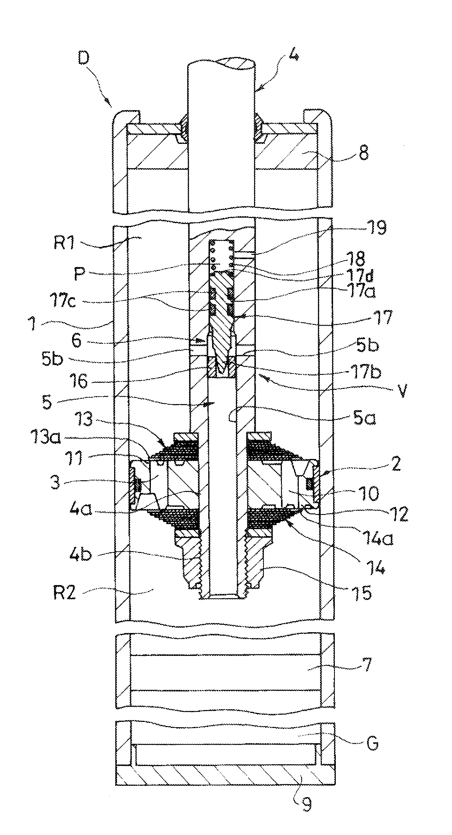
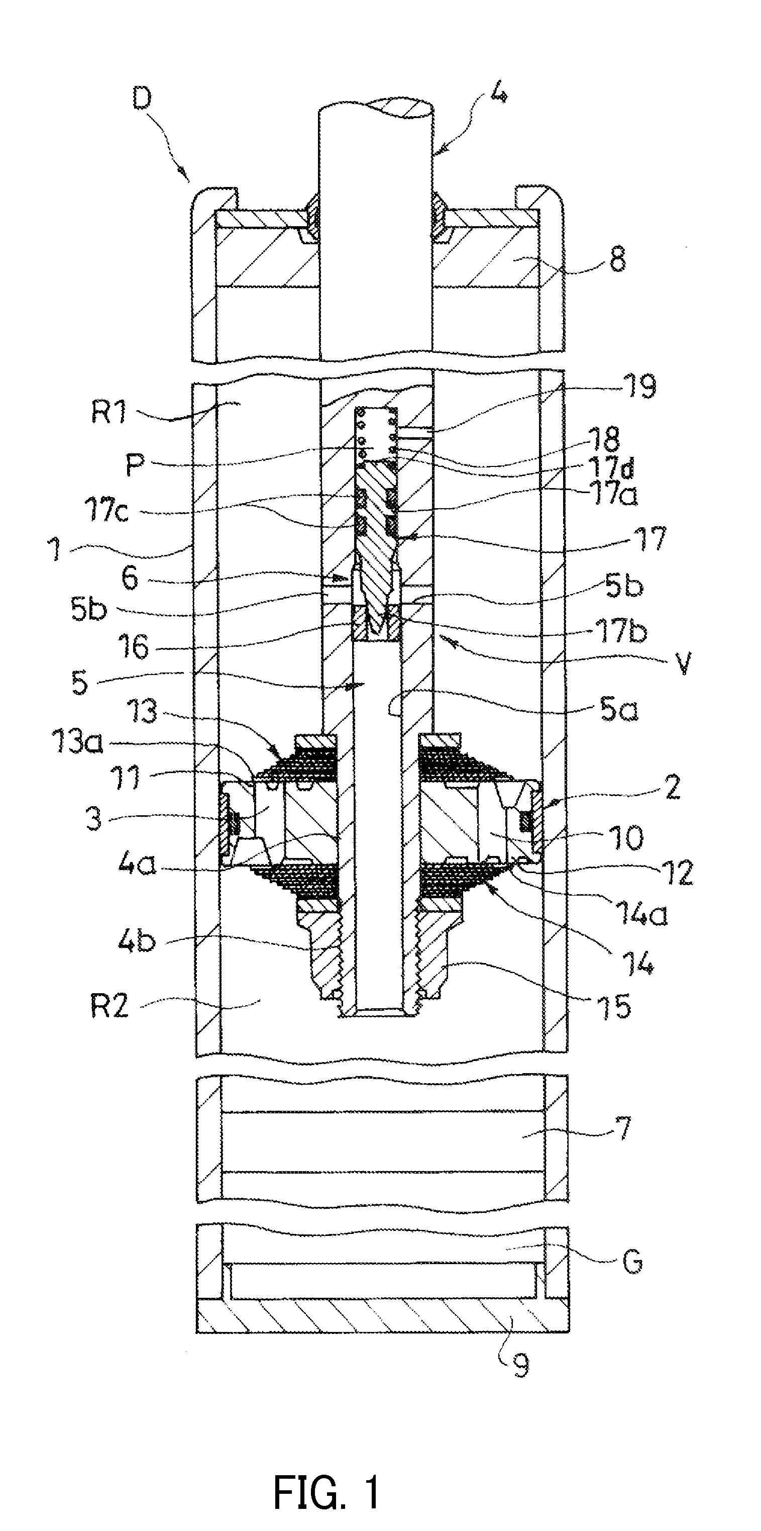
[0021]As shown in FIG. 1, a damping valve V in the present embodiment is applied to a damper D. The damping valve V includes a piston 2 movably inserted into a cylinder 1 and partitioning an interior of the cylinder 1 into an extension side chamber R1 and a pressure side chamber R2, a damping passage 3 provided in the piston 2 and communicating between the extension side chamber R1 and the pressure side chamber R2, a piston rod 4 movably inserted into the cylinder 1 and of which one end (lower end in the FIG. 1) is coupled to the piston 2, a bypass 5 provided in the piston rod 4 and communicating the pressure side chamber R2 with the extension side chamber R1 by bypassing the damping passage 3, and a relief valve 6 releasing the bypass 5 upon an action of a pressure of the pressure side chamber R2.
[0022]The damper D includes the cylinder 1, the piston 2, the piston rod 4, and a free piston 7 slidably inserted into the cylinder 1 and partiti...
second embodiment
[0054]A second embodiment will be described.
[0055]In the damper D to which the damping valve V of the first embodiment is applied, in a case where the damping characteristic at the time of the contraction operation of the damper D is tuned to match with preference of a user, there is a need for taking the damping valve V out from the damper and replacing the bias spring 18.
[0056]Thus, in the present embodiment, a damping valve V capable of easily tuning the damping characteristic at the time of the contraction operation of the damper D will be described.
[0057]As shown in FIG. 3, the damping valve V in the present embodiment is applied to the damper D. Since configurations of part of the damper D and the damping valve V are the same as the first embodiment, the description thereof will be omitted, and only different parts will be described.
[0058]In the present embodiment, the relief valve 6 further includes an adjustment mechanism 20 adjusting the bias force of the bias spring 18, an...
third embodiment
[0071]A third embodiment will be described.
[0072]In the first embodiment, among the damping characteristic of the damper D after opening the relief valve 6, a retreat displacement amount of the valve body 17 from the annular valve seat 16 after opening the relief valve 6 is considered to be managed by controlling the pressure in the back pressure chamber P in addition to changing a spring constant of the bias spring 18. The pressure in the back pressure chamber P is controlled by a magnitude of resistance applied to the passing fluid by the throttle 19, specifically by the flow passage area of the throttle 19.
[0073]Therefore, in the damping valve V of the first embodiment, by setting the flow passage area of the throttle 19 to an area to realize a target damping characteristic in advance, the damping characteristic can be tuned.
[0074]It should be noted that when the damping characteristic is tuned only by the spring constant of the bias spring 18, not only the gradient of the dampin...
PUM
 Abstract
Description
Claims
Application Information
 - R&D
- Intellectual Property
- Life Sciences
- Materials
- Tech Scout
- Unparalleled Data Quality
- Higher Quality Content
- 60% Fewer Hallucinations
Browse by: Latest US Patents, China's latest patents, Technical Efficacy Thesaurus, Application Domain, Technology Topic, Popular Technical Reports.
© 2025 PatSnap. All rights reserved.Legal|Privacy policy|Modern Slavery Act Transparency Statement|Sitemap|About US| Contact US: help@patsnap.com


