Device for mechanical connection of a control surface to a fixed structural element of an aircraft and aircraft wing element equipped with said device

a technology for aircraft and structural elements, applied in aircraft transmission means, aircraft power plants, transportation and packaging, etc., can solve the problems of increasing the dimensions and mass of the structure, the operation device of the control surface, and the mechanism involving considerable linear operating forces, etc., to achieve the effect of simple, economic and efficacious

Active Publication Date: 2014-01-02
AIRBUS OPERATIONS (SAS)
View PDF1 Cites 41 Cited by
  • Summary
  • Abstract
  • Description
  • Claims
  • Application Information

AI Technical Summary

Benefits of technology

[0027]The aim of the invention especially is to provide a solution which is simple, economic and efficacious for the pr

Problems solved by technology

But there are disadvantages associated with control surface operating devices of the type comprising a linear jack.
In fact, these mechanisms involve considerable linear operating forces.
These forces must be absorbed by the structure of the fixed part of the wing and by the structure of the control surface, which also results in increase in the dimensions and the mass of these structures.
Yet, growing demands for reduction in fuel consumption are compelling aircraft manufacturers to reduce both the weight of future units as well as their drag coefficient, especially by decreasing the thickness of the tailplanes and main wings, to the detriment of the volume available for devices provided for operating the control surfaces.
In addition, increasing operating speeds of the control surfaces made preferable by the development of pilotage laws of aircrafts causes an increase in the required volume of the jacks, which all the more complicates integrati

Method used


Image

  • Device for mechanical connection of a control surface to a fixed structural element of an aircraft and aircraft wing element equipped with said device
  • Device for mechanical connection of a control surface to a fixed structural element of an aircraft and aircraft wing element equipped with said device
  • Device for mechanical connection of a control surface to a fixed structural element of an aircraft and aircraft wing element equipped with said device

Examples


first embodiment

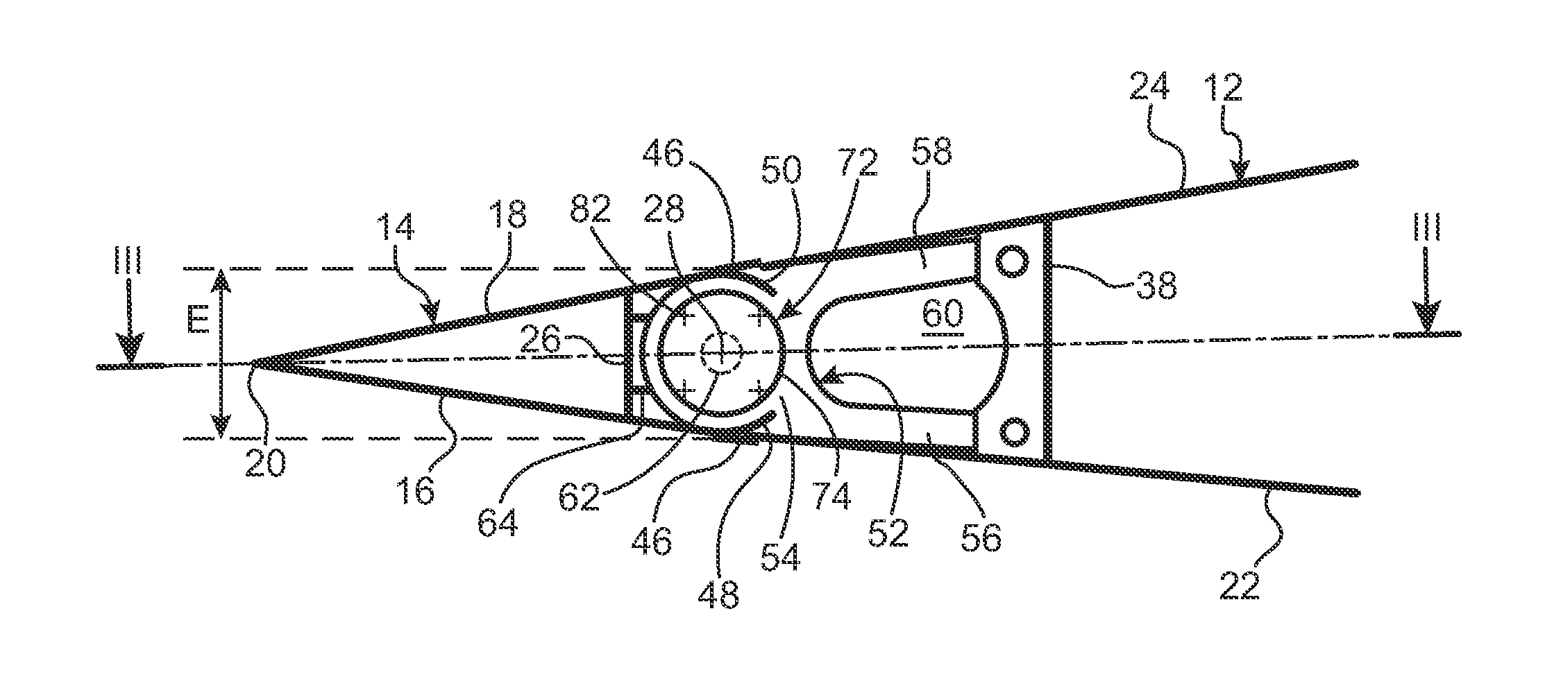
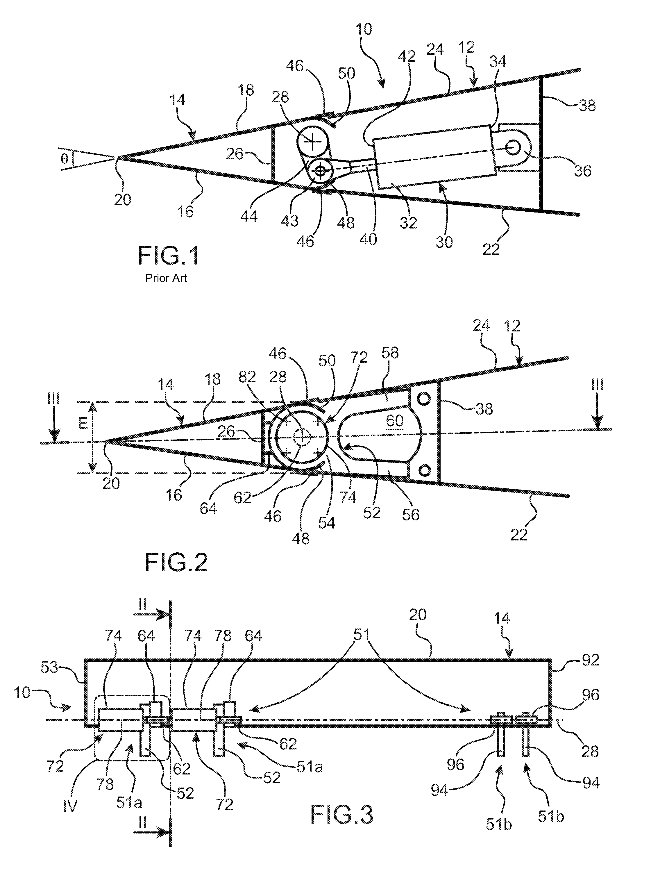
[0096]The wing 10 according to this first embodiment differs from the wing of FIG. 1 essentially by the aileron 14 which is mechanically connected to the fixed part 12 of the wing.

[0097]This mechanical connection is ensured by a device 51 comprising two articulation and operating subassemblies 51a, arranged near a first longitudinal end 53 of the aileron 14, the constitutive elements of which will now be described, as well as two articulation subassemblies 51b which will be described subsequently.

[0098]Each of these articulation and operating subassemblies 51a comprises a support element 52 extending according to the plane of FIG. 2 and having overall for example the form of a U with concavity turned in the direction opposite the trailing edge 20. More precisely, the support element 52 comprises a control surface articulating part 54, from which extend a lower leg 56 and an upper leg 58, whereof the free respective ends are connected to the rear spar 38 of the fixed part 12 of the w...

fourth embodiment

[0131]As a variant, the connection between the finger 102 and the lever 76 can be made by means of a more sophisticated articulation, for example of the type to be described hereinbelow in relation to the invention. Also, the configuration can be reversed, that is, the finger 102 can be borne by the lever 76, in which case the articulation and operating subassembly 51a comprises an engagement element connected to the closing spar 26 of the aileron 14 and in which the abovementioned finger 102 is engaged.

[0132]By analogy with the first embodiment described hereinabove, the support element 52 and the control surface fitting 64 can be of more robust design without departing from the scope of the present invention, and in particular can form respectively a female part and a male hinge part.

[0133]The operation of the wing 10 according to this third embodiment differs from that of the wing according to the first embodiment described hereinabove in that the motor torque induced by each rot...

fifth embodiment

[0145]Three of the articulation subassemblies 51b are arranged to the side of the first longitudinal end 53 of the aileron 14, whereas the two other articulation subassemblies 51b are arranged to the side of the second longitudinal end 92 of the latter as in the embodiments described hereinabove. The articulation subassemblies 51b of this fifth embodiment are similar to those of the embodiments described hereinabove.

[0146]The two operating subassemblies 51a are each inserted between two consecutive articulation subassemblies 51b located to the side of the first longitudinal end 53 of the aileron 14.

[0147]Each operating subassembly 51a comprises a rotary actuator 72 provided with a lateral mounting plate 104 fixed to the closing spar 26 of the aileron 14, as in the fourth embodiment described hereinabove, so as to align the output axis 78 of the actuator with the axis of articulation 28 defined by the articulation subassemblies 51b.

[0148]The output member 76 of the actuator 72 takes...


PUM


Abstract

A device for mechanically connecting a control surface to a fixed structural element of an aircraft, including a rotary actuator for driving an element that is securely connected to the control surface in rotation in relation to an element securely connected to the fixed structural element, around an articulation axis, as well as articulation elements for articulating this control surface around this axis. These articulation elements are able to support the control surface independently of the rotary actuator. This arrangement permits taking benefit from the advantageous properties of rotary actuators while allowing removal of the rotary actuator without having first to remove the control surface.

Description

CROSS-REFERENCES TO RELATED APPLICATIONS[0001]This application claims the benefit of the French patent application No. 12 56113 filed on Jun. 27, 2012, the entire disclosures of which are incorporated herein by way of reference.BACKGROUND OF THE INVENTION[0002]The present invention relates to a device for mechanical connection of a control surface to a fixed structural element of an aircraft.[0003]It relates in particular to articulation and operating means of a control surface on a fixed structural element of a wing element of an aircraft.[0004]In this respect, throughout this description the term “wing element” means any aerodynamic bearing surface of an aircraft, such as a principal wing, or a horizontal or vertical tailplane.[0005]The invention also relates to such a wing element of an aircraft, and an aircraft equipped with same.[0006]A wing element overall has two aerodynamic surfaces which join both at the level of the leading edge and also at the level of the trailing edge o...

Claims


Application Information

Patent Timeline
IPC IPC(8): B64C13/28
CPCB64C13/28B64C9/02Y02T50/40B64C3/48B64C3/50
Inventor TIEYS, PIERRESAGANSAN, ALAINANDRIEU, LAURENT
Owner AIRBUS OPERATIONS (SAS)
Why Eureka
Try Eureka